


38
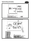
Standard control features
• 4 in. x 4 in. junction box
NOTE: Motor leads are wired to the 4 in. x 4 in. junction
box, mounted on the external panel. Field verification of
the motor rotation is required on 3-phase applications.
Motor control options
• Interlocking disconnect switch*
• 24-v class 2 transformer (40 va)†
• 8-pole control terminal strip
• Motor power fusing*
• Motor control contactor**
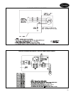
Motor and electric heat control options
NOTE: Electric heat option requires same voltage as motor
and must include the control option. These control features
are standard with electric heat options and control option.
• Interlocking disconnect switch*
• Heater power fusing*
• 24-v class 2 transformer (40 va)†
• 8-pole control terminal strip
• Auto reset temperature limit switch
• Manual reset backup temperature limit switch
• 80/20 heater element wire
• Motor power fusing*
• Motor control contactor**
• Agency listed for 0-in. clearance
Electric heat options:
• Single-phase, 1 or 2 stage heat
• Three-phase, 1, 2 or 3 stage heat
*Complies with NEC’s requirement, Article 430 for dis-
connect, branch circuit protection motor controller and
motor overload protection.
†No control fusing necessary.
**Complies with NEC’s requirement for a motor starter
with internal heating elements when used with the
factory’s standard motors with integral thermal overload
protection.
Controls