


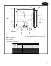

20
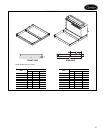
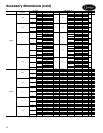
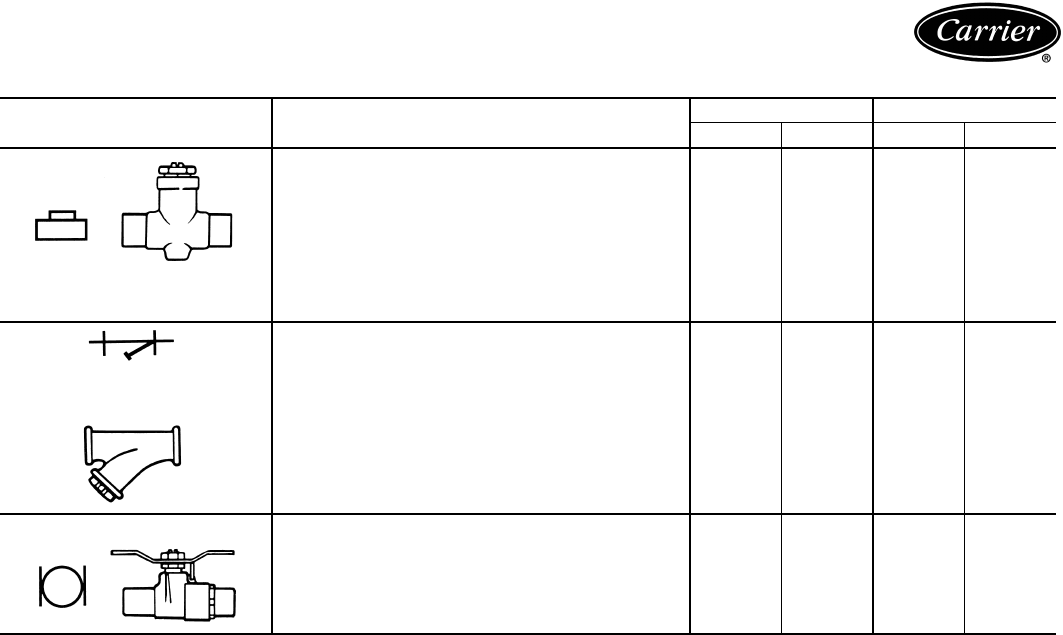
PIPING COMPONENTS (cont)
LEGEND
*Check all system component pressure ratings (coils, values, pumps,
etc.) with manufacturer and any applicable local or national piping
codes prior to specifying system pressure rating.
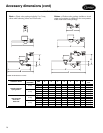
SYMBOL/SKETCH DESCRIPTION
C
V
FACTOR RATING*
1
/
2
3
/
4
PSI F
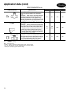
BALANCE VALVE: Variable water flow manual bal-
ancing valve with screwdriver slot adjustment
screw.
Application — Often used in conjunctionwithtest
port fittings for water flow balancing. Balance by
temperature differential or coil pressure drop
(check specifications for service fittings required if
balancing by pressure drop). May be used in 3-way
valve bypass line to permit equal flow balancing.
3.0 8.9 150 200
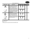
STRAINER: Y-type body with 50 mesh stainless
steel screen.
Application — Used for removal of small particles
from system water during normal system operation.
Should not be used in lieu of main system strain-
ers. Strainer screen may have to be removed dur-
ing initial high pressure system flushing during
start-up. Screen should be removed and cleaned
per normal maintenance schedule (provisions for
strainer blow-down not provided).
9.0
Clean
19.0
Clean
400 250
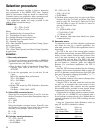
BALL VALVE: Manual balance and shut-off valve.
Application — Used for unit isolation and water flow
balancing. Without memory stop feature water bal-
ance point must be marked by installer (if neces-
sary). Check specifications for service fittings
required when used for water balancing.
4.0 7.5 400 200
Cv — Coefficient of Velocity
DX— Direct Expansion
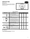
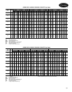
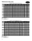
Application data (cont)