


22
This selection procedure provides a guide to determine
unit performance of the 42BHC, BVC units. Capacity
tables (in Performance Data) are based on nominal cfm.
Correction factors are provided for other operating condi-
tions as explained in the following selection example.
For applications outside the range provided in this
catalog, please consult the factory.
FORMULAS:
TC = TCb x Ct x Et
SC = SCb x Cs x Es
Where:
Cs = Sensible Airflow Correction Factor
Ct = Total Airflow Correction Factor
Es = Sensible Elevation Correction Factor
Et = Total Elevation Correction Factor
SC = Sensible Capacity
SCb = Base Sensible Capacity from Base Cooling Capaci-
ties by gpm charts
TC = Total Capacity
TCb = Base Total Capacity from Base Cooling Capacities
by gpm charts
EXAMPLE:
I Rate unit performance.
To rate the performance at sea level for a 42BHC16
unit with a four-row coil at 80 F/67 F EAT, 45 F EWT,
7 gpm water flow, and 1500 cfm:
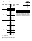
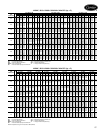
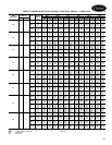
a) Enter the Base Cooling Capacities by Gpm, 4-Row
Capacity Units table at 80 F/67 F EAT and
45 F EWT.
b) Locate the appropriate row for unit size 16 and
7 gpm.
Record the tabulated base performance.
TCb = 42.0 MBtuh
SCb = 34.2 MBtuh
∆T = 12.0 F
c) Divide CFM Actual by CFM Nominal to determine
Cfm Ratio.
Cfm Ratio = 1500/1600 =.9375
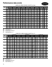
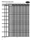
II Select CFM correction factors.
Select the Cfm correction factors, Ct and Cs, from the
Airflow Correction Factors table. (Interpolation may be
required.)
Ct = .9625
Cs = .96
Select the elevation correction factors, Et and Es, from
the Elevation Correction Factors table. (No correction
necessary in this example, unit is at sea level.)
Et = 1.00
Es = 1.00
III Calculate actual performance.
TC = TCb x Ct x Et
= 42.0 x .9625 x 1.00
= 40.42 MBtuh
SC = SCb x Cs x Es
= 34.2 x .96 x 1.00
= 32.83 MBtuh
a) Calculate water pressure drop (or refer to the Water
Pressure Drop for Cv Factor and Water Flow Rate
table on page 33). From the Cv Factor by Coil and
Unit Size table on page 32, find the Cv value for
unit size 16 with four rows.
Cv = 7.2
P = [GPM/(0.658 x Cv)]2
= [7.0/(0.658 x 7.2)]2
= 2.18 feet of H
2
O
b) For selections other than those listed here, please
contact the factory.
IV Determine motor.
To determine motor and drive selection requirements
and obtain the cfm for a specific application, the
total static pressure (TSP) for that application must be
determined.
The TSP is the sum of the internal static pressure
(ISP) and the external static pressure (ESP) measured in
inches of water column. Internal static pressure is the
sum of the static resistance of the unit’s components
— the cabinet, coil and filter. The ESP is the static
resistance of the unit’s external components, including,
but not limited to, ductwork, grilles and additional
filtration. For non-ducted applications, the ESP is
0 in. wg.
After the TSP has been calculated (see the following
example), use the motor horsepower table on pages 30
and 31 to determine actual horsepower (hp) for the belt
drive unit. Horsepower offerings are limited to
1
/
4
,
1
/
3
,
1
/
2
,
3
/
4
, 1, 1
1
/
2
, 2, 3 and 5.
The standard selection is the nearest offering above
the actual hp shown in the table.
Using the TSP of the table, match the unit size with
the cfm row to determine the correct motor for the
specific application. Drive sheaves and the required
belt assembly will be provided to meet specific design
requirements. Drive sheaves are set at the factory.
Calculate the hp and drive selection required to deliv-
er 1500 cfm on a 42BHC16 unit equipped with a
4-row hydronic cooling coil and a 2-in. pleated filter in
a ducted application at .38 in. ESP, including duct and
grille losses.
Using the Component Static Resistance table on
page 32, the ISP is calculated as follows:
Cabinet .09-in. wg
4-row Wet Coil .30-in. wg
2-in. Pleated Filter .12-in. wg
ISP .51-in. wg
ESP .38-in. wg
TSP .89-in. wg
Selection procedure