


17
C
D
HWS
B
A
2(51)
RH Tell-Tale
Drain
LH Tell-Tale
0
CWS
CWR
HWR
1-5/8(41)
)462(8/3-01
E
F
)912(8/5-8
H
G
)571( 8/7-6
0
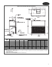
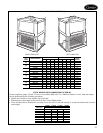
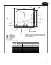
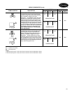
PIPING CONNECTION LOCATION DIAGRAM*
LEGEND
*Right-hand unit with re-heat coil shown.
CWR — Cold Water Return
CWS — Cold Water Supply
HWR — Hot Water Return
HWS — Hot Water Supply
LH — Left Hand
RH — Right Hand
SO — Stub Out
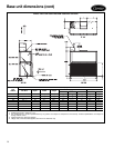
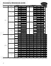
42BHC,BVC
UNIT SIZE
HEAD STUB OUT SIZES (in.)
8RowCoilSO
Nominal
6RowCoilSO
Nominal
4RowCoilSO
Nominal
Heating 1 or 2 SO
Row Coil Nominal
06 1 0.75 0.75 0.5
08 1 0.75 0.75 0.5
10 1 0.75 0.75 0.5
12 1 0.75 0.75 0.5
16 11 1 0.5
20 11 1 0.5
30 1.5 1.5 1.5 0.5
40 1.5 1.5 1.5 0.5
Use the table on the next page to determine the location of the piping
connections. For example, on a size 20 unit with 4 rows and a right
hand connection, the location of the chilled water supply line is deter-
mined by G (6 in.) and B (7
4
/
5
in.).