


49
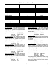
ZONE MAINTENANCE TABLE — The Zone Maintenance
table is used to display zone set points and variables. See
Table 16.
Occupied
— This variable indicates if the zone controller is
operating in the occupied mode.
Occupied: Display Range No/Yes
Default Value No
Network Access Read Only
Linkage Slave
— This variable displays if air source linkage is
in effect.
Linkage Slave: Display Range No/Yes
Default Value No
Network Access Read Only
Linkage Master
— This variable displays if this zone control-
ler is functioning as a linkage master.
Linkage Master: Display Range No/Yes
Default Value No
Network Access Read Only
Timed Override in Effect
— This variable indicates if a timed
override is in effect.
Timed Override
in Effect: Display Range No/Yes
Default Value No
Network Access Read Only
Set Point Offset (T-56)
— This variable displays the degrees
of offset when using a 33ZCT56SPT space temperature sensor
with set point adjustment. The slidebar on the sensor will adjust
the desired temperature in that zone, up or down, when it is
moved. The Set Point Offset (T-56) variable can disable set
point offset (set to 0).
Set Point
Offset (T-56): Display Units delta F (delta C)
Display Range 0.0 to 15.0
Default Value 0.0
Network Access Read Only
Cool Master Reference
— This variable displays the cooling
master reference from the set point schedule. This should be
the occupied cool set point when the zone is in occupied
mode or the unoccupied cool set point when the zone is in
unoccupied mode. This variable will display any space temper-
ature sensor slidebar offset that is being applied.
Cool Master
Reference: Display Units F (C)
Display Range 45.0 to 99.9
Default Value 90.0
Network Access Read/Write
Primary Damper Airflow Reference
— This variable dis-
plays the current controlling airflow set point.
Primary Damper
Airflow Display Units CFM
Reference: Display Range 0 to 9999 (Limited by
velocity pressure transducer high alarm
limit)
Default Value 0
Network Access Read /Write
Primary Damper Position
— This variable displays the cur-
rent damper position.
Primary Damper
Position: Display Units % (open)
Display Range 0 to 100
Default Value 100
Network Access Read/Write
Secondary Damper Airflow Reference
— This variable dis-
plays the current controlling airflow set point for the secondary
damper.
Secondary Damper
Airflow Display Units CFM
Reference: Display Range 0 to 9999 (Limited by
velocity pressure transducer high alarm
limit)
Default Value 0
Network Access Read /Write
Heat Enable
— This variable displays the demand for heat in
the space. The space temperature must be below the appropri-
ate heat set point.
Heat Enable: Display Range Dsable/Enable
Default Value Dsable
Network Access Read Only
→
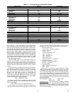
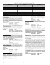
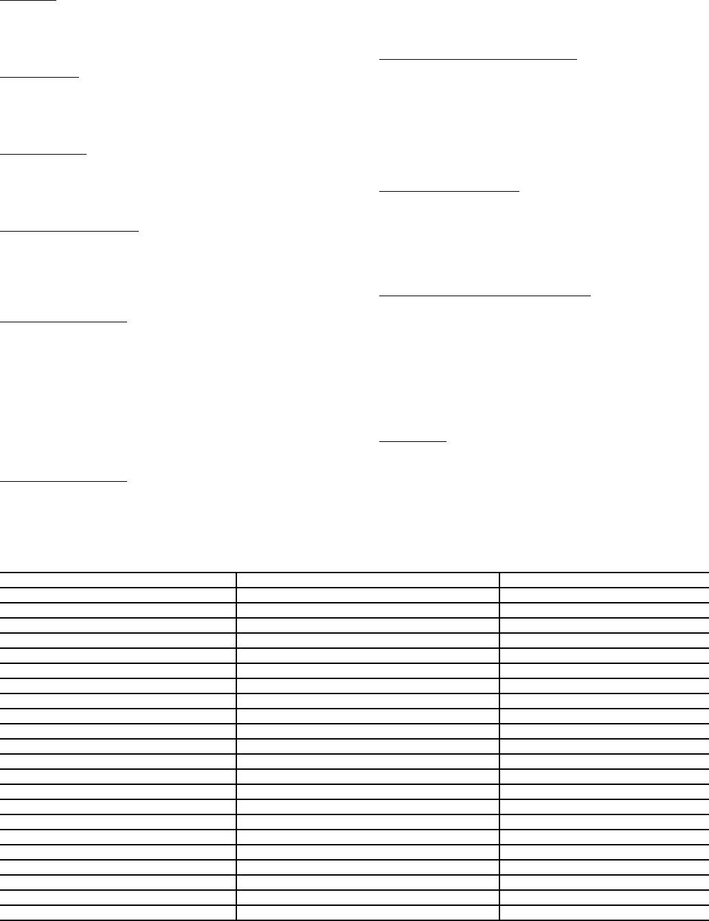
Table 16 — Zone Maintenance Table
DESCRIPTION DEFAULT POINT NAME
Occupied
No ZONEOCC
Linkage Slave
No DAVCTL
Linkage Master
No LINKMAST
Timed Override in Effect
No TIMOV
Set Point Offset (T-56)
0.0 F T56OFF
Cool Master Reference
90.0 F CCMR
PI Primary Damper Reference
0 cfm PISMR
PD Primary Damper Reference
100 % PDSMR
Secondary Damper Reference
0 cfm SDSMR
Heat Enable
Dsable HEATENA
Heat Master Reference
55.0 F HCMR
Heat Submaster Reference
0 F HSMR
Temperature Control Airflow
100 % TCA
Relative Humidity Airflow
0 % RHA
Air Quality Airflow
0 % AQA
Cooling in Effect
Yes COOLFLAG
Heating in Effect
No HEATFLAG
RH in Effect
No RHFLAG
AQ in Effect
No AQFLAG
Unoccupied Dehumidification
No UNOCCDH
Cooling Energy
0 Btu COOLBTUS
Heating Energy
0 Btu HEATBTUS
801
→