


41
Start Value: Units F (C)
Range 40 to 125
Default Value 80
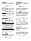
Ducted Heat
— The Ducted Heat configuration is used to con-
figure the terminal for ducted heat. If a local heat source is in
the duct and requires airflow to provide heat, set the Ducted
Heat configuration for yes.
Ducted Heat Range No/Yes
Default Value Yes
Maximum Duct Temperature
— This configuration is used to
configure the maximum supply-air temperature desirable for
heating the space. This will cause the heat to be modulated or
cycled using this value as the maximum temperature of the air
to be supplied.
Maximum Duct
Temperature: Units F (C)
Range 40 to 200
Default Value 110
Number of Electric Stages
— This configuration is used to
define the number of stages of electric heat controlled by the
zone controller.
Number of
Electric Stages: Range 1 to 3
Default Value 1
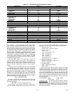
Heat On Delay
— The Heat On Delay configuration is used to
define a delay from the time a parallel terminal fan is started
until the heat is activated.
Heat On Delay: Units minutes
Range 1 to 60
Default Value 2
Fan Off Delay
— The Fan Off Delay configuration is used to
define a delay time. The delay time is from when the heat is de-
activated (in a parallel terminal) until the parallel fan is deacti-
vated. This allows the fan to circulate air and remove the resid-
ual heat from the heat source.
Fan Off Delay: Units minutes
Range 1 to 15
Default Value 2
Two-Position Heat Logic
— This configuration is used for
controlling a normally closed or normally open valve for hot
water. Use normal logic if the valve is normally closed. Use in-
verted logic if the valve is normally open.
Two Position
Heat Logic: Range Normal/Invert
Default Value Normal
Space Temperature Trim
— This configuration is used to trim
a space sensor which might need calibration. For example, if
the temperature displayed is two degrees above the value mea-
sured with calibrated test equipment, input a value of –2.0.
Space Temperature
Trim: Units delta F (delta C)
Range –9.9 to 9.9
Default Value 0.0
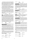
Supply Air Temperature Trim
— This configuration is used
to trim a supply air sensor which might need calibration. For
example, if the temperature displayed is two degrees above the
value measured with calibrated test equipment, input a value of
–2.0.
Supply Air Temperature
Trim: Units delta F (delta C)
Range –9.9 to 9.9
Default Value 0.0
Remote Contact Config
— The remote timeclock contact in-
put can be configured as a normally open or normally closed
contact. When the timeclock input is ‘On’ the zone will follow
it’s local occupancy schedule. When the timeclock input is
‘Off’ the zone will be forced into unoccupied state.
Remote Contact
Config: Range Close/Open
Default Value Close
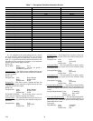
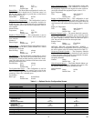
OPTIONS SERVICE CONFIGURATION SCREEN —
The Options Service Configuration screen is used to configure
the service options of the air terminal controller. See Table 11.
Occupancy Schedule Number
— The Occupancy Schedule
Number defines what Occupancy schedule the zone controller
will use. Occupancy Schedule 64 is a local schedule. Occupan-
cy Schedules 65 to 99 are global schedules.
Occupancy Schedule
Number: Range 64 to 99
Default Value 64
Global Schedule Master
— The Global Schedule Master con-
figuration allows the Occupancy Schedule to be used as a Glo-
bal Schedule Master (Occupancy Schedules 65-99).
Global Schedule
Master: Range No/Yes
Default Value No
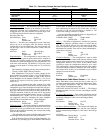
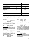
Table 11 — Options Service Configuration Screen
DESCRIPTION DEFAULT POINT NAME
Occupancy Schedule Number
64 SCH
Global Schedule Master
No GSM
Override
00:00 OVR
Broadcast Acknowledge
No BCACK
Set Point Group Number
0SETT
Global Set Point Master
No GSTM
Maximum Offset Adjust
2 F LIMT
Control Options
0CTLOPT
Humidity
Proportional Gain
Integral Gain
Maximum Output Value
1.5
0.30
100.0 cfm
KP
KI
MAXOUT
Air Quality
Proportional Gain
Integral Gain
Maximum Output Value
0.10
0.03
100.0 cfm
KP
KI
MAXOUT
AQ Low Voltage
0.0 AQINLO
AQ High Voltage
10.0 AQINHI
AQ Low Reference
0 ppm AQLO
AQ High Reference
2000 ppm AQHI
801
→