


37
Air Quality
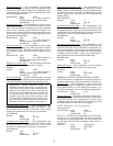
— The Air Quality set point is used to configure
the IAQ set point for the zone controller if optional controlled
ventilation support is used.
Air Quality Units none shown (ppm
(ppm): implied)
Range 0 to 5000
Default Value 850
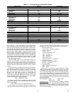
Delta Airflow
— The Delta Airflow set point is used to con-
figure the Delta Airflow set point for the zone controller if the
zone pressure control option is used. If a negative pressure is
desired, configure the value as a positive delta.
Delta Airflow: Units cfm
Range -9999 to 9999
Default Value 0
Service Configuration Selection Screen —
The
Service Configuration Selection screen is a menu of Service
screens which can be accessed by the user. The following
screens are available: Airflow Service Configuration, Terminal
Service Configuration, Option Service Configuration, and Sec-
ondary Damper Service Configuration.
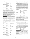
AIRFLOW SERVICE CONFIGURATION SCREEN —
The Airflow Service Configuration Table is used to configure
the pressure independent and backup pressure dependent set
points. See Table 9.
Pressure Independent
— Pressure Independent (PI) set points
should be configured for pressure independent operation
applications.
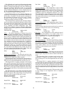
Cool Minimum (PI)
— This configuration is the minimum
airflow the terminal will control to when the equipment is in
Cooling mode (or Fan Only mode) or free cooling. The space
requirements for cooling must be at a minimum, or the terminal
is a fan powered terminal and the space requirements are for
heat.
Cool Minimum: Units CFM
Range 0 to 9999 (Limited by
the High Velocity pressure limit alarm)
Default Value 0
Cool Maximum (PI)
— This configuration is the maximum
airflow the terminal will control to when the equipment is in
Cooling mode (or Fan Only mode) or free cooling and the
space requirements for cooling are at a maximum.
Cool Maximum: Units CFM
Range 0 to 9999 (Limited by
the High Velocity pressure limit alarm)
Default Value 4000
Terminal Reheat (PI)
— This configuration is for single duct
units with ducted reheat. The desired airflow is configured at
which the reheat will provide optimum performance. This val-
ue is compared to the Minimum Cool value and the greater of
the two values is used to determine the airflow set point.
Terminal Reheat: Units CFM
Range 0 to 9999 (Limited by
the High Velocity pressure limit alarm)
Default Value 0
→
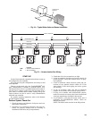
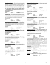
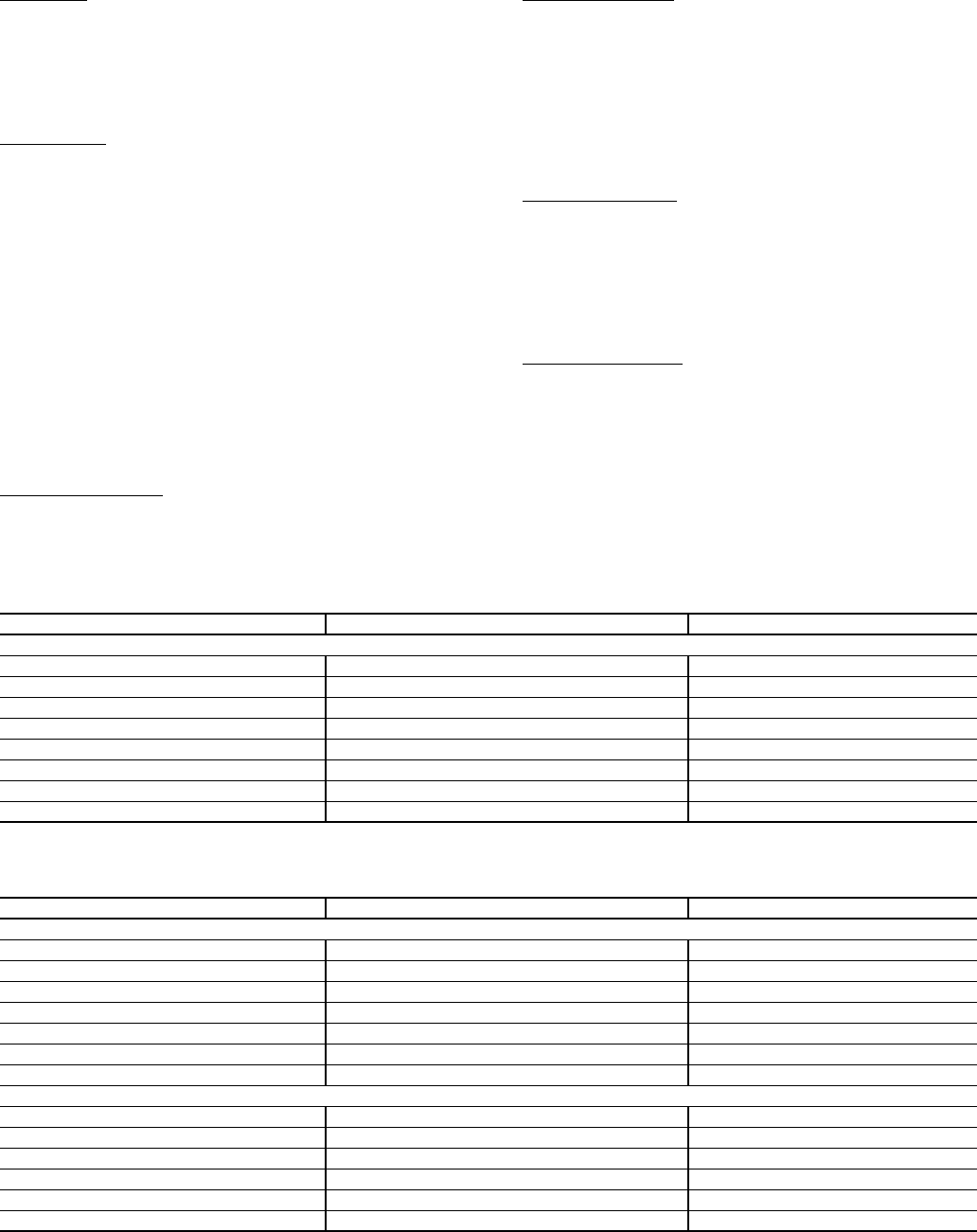
Table 8 — Set Point Screen
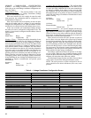
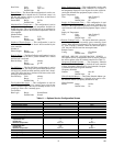
Table 9 — Airflow Service Configuration Screen
DESCRIPTION DEFAULT POINT NAME
Set Points
Occupied Heat
70.0 F OHSP
Occupied Cool
74.0 F OCSP
Unoccupied Heat
55.0 F UHSP
Unoccupied Cool
90.0 F UCSP
Occupied HIgh Humidity
60.0 % ORHH
Unoccupied High Humidity
100 % URHH
Air Quality (ppm)
850 ppm AQSP
Delta Airflow
0 cfm DCFM
DESCRIPTION DEFAULT POINT NAME
Pressure Independent
Cool Minimum
0 cfm COOLMIN
Cool Maximum
4000 cfm COOLMAX
Terminal Reheat
0 cfm REHEAT
Heat Minimum
0 cfm HEATMIN
Heat Maximum
4000 cfm HEATMAX
Parallel Fan On
0 cfm FNONCFM
Dual Duct CV Airflow
4000 cfm DDCVFLOW
Pressure Dependent
Cool Minimum Position
0 % CMINPOS
Cool Maximum Position
100 % CMAXPOS
Reheat Minimum Position
0 % REMINPOS
Heat Minimum Positon
0 % HMINPOS
Heat Maximum Position
100 % HMAXPOS
Deadband Percent
12.5 % DB_PCT
1001