


27
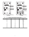
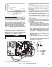
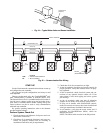
3. Connect the other end of the communication bus cable
to the terminal block labeled CCN in the zone control-
ler of the first air terminal. Following the color code
in Table 3, connect the Red (+) wire to Terminal 1.
Connect the White (ground) wire to Terminal 2. Con-
nect the Black (–) wire to Terminal 3.
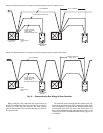
4. Connect additional zone controllers in a daisy chain
fashion, following the color coded wiring scheme in
Table 3. Refer to Fig. 25.
NOTE: The communication bus drain wires (shield) must
be tied together at each zone controller. If the communica-
tion bus is entirely within one building, the resulting contin-
uous shield must be connected to ground at only one single
point. If the communication bus cable exits from one build-
ing and enters another building, connect the shields to
ground at a lightning suppressor in each building where the
cable enters or exits (one point only).
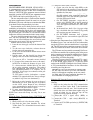
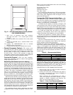
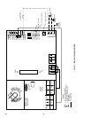
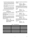
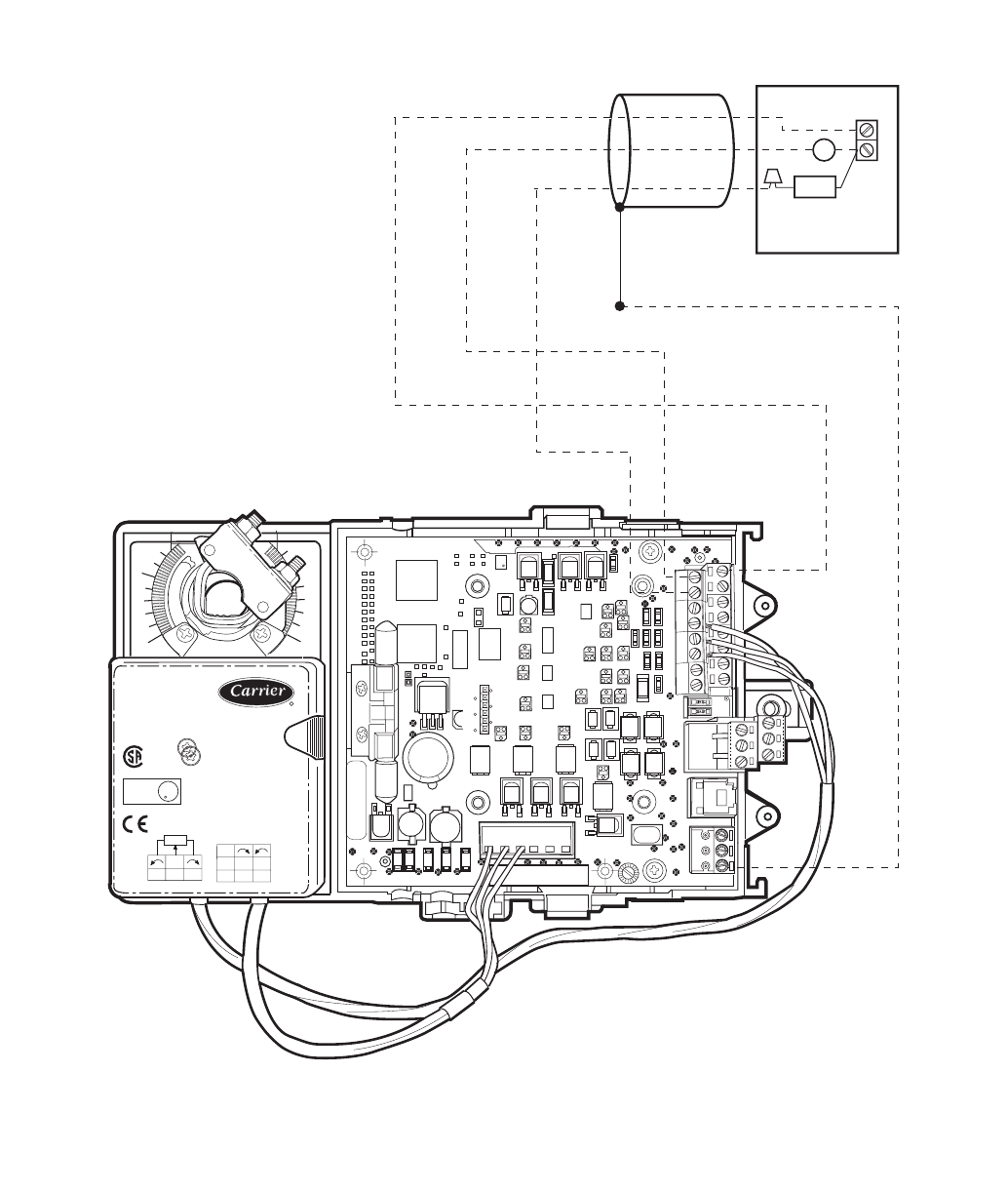
+
-
499
RESISTOR
(SUPPLIED
W/SENSOR)
HUMIDITY SENSOR
RED
WHITE
BLACK
3 CONDUCTOR
20 AWG CABLE
SHIELD
(IF USED)
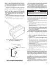
35 in-lb (4 Nm)
80...110s
HF23BJ042
Made in Switzerland
by Belimo Automation
1
0
yel
blu
ora
WIP
5K
LISTED
94D5
TEMP. IND. &
REG. EQUIP.
U
L
Class 2 Supply
LR 92800
NEMA 2
24VAC/DC
50/60Hz
3VA 2W
COM
1
2
3
blk
red
wht
+24V
RH/IAQ
GND
Fig. 22 — Humidity Sensor Wiring