


48
→
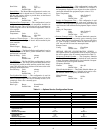
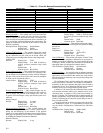
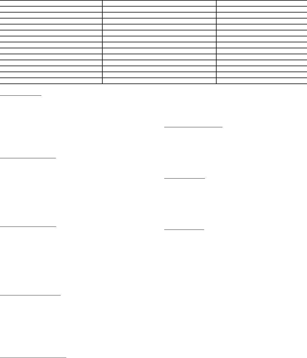
Table 15 — Zone Air Balance/Commissioning Table
Heating Override
— This variable can be used to test the heat
outputs. Enabling this variable will cause the heat to be modu-
lated or staged to full heat until this point is disabled or the
force released. Ducted reheat operation will be controlled so as
not to exceed the configured maximum duct temperature. The
supply-air temperature is included on this screen to verify that
the heat is operating.
Heating Override: Display Range Dsable/Enable
Default Value Dsable
Network Access Read /Write
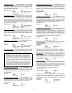
Airflow CFM Set Point
— This variable displays the current
airflow set point that the zone controller is controlling to. Dur-
ing the calibration tests this value can be forced, which will
change the set point configuration for the value being tested.
Airflow CFM
Set Point: Display Units CFM
Display Range 0 to 9999 (Limited by
velocity pressure transducer high alarm
limit)
Default Value 0
Network Access Read /Write
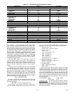
Actual Airflow Display
— This variable shows the actual air-
flow being measured, based on the inlet size configured. Dur-
ing the Maximum and Minimum Cooling Airflow calibration
tests this value can be forced, which will correct the multiplier
or offset used to calculate the airflow.
Actual Airflow: Display Units CFM
Display Range 0 to 9999 (Limited by
velocity pressure transducer high alarm
limit)
Default Value 0
Network Access Read /Write
Primary Damper Position
— This variable displays the cur-
rent damper position. During CFM Balancing, this variable is
used to display the position of the damper. This value can
be used to see if the damper is fully open and the system air is
sufficient.
Primary Damper
Position: Display Units % (open)
Display Range 0 to 100
Default Value 100
Network Access Read Only
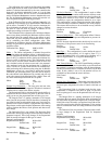
Measured Velocity Pressure
— This variable displays the
measured velocity pressure, which is used to check accuracy
during test and balancing of the terminal. If the pressure
appears to be much different than that measured with a Magna-
helic gage, the transducer can be forced to recalibrate its zero
by enabling the Damper/Transducer Calibration.
Measured Velocity
Pressure: Display Units in. wg
Display Range 0.000 to 2.000 (Limited
by velocity pressure transducer high alarm
limit)
Default Value 0.000
Network Access Read Only
Supply-Air Temperature
— This variable displays the supply-
air temperature for ease of verifying the heat operation during
the heat test.
Supply-Air
Temperature: Display Units F (C)
Display Range -40.0 to 245.0
Default Value 0.0
Network Access Read /Write
Auto-Calibration
— This variable will display “Normal” if the
actuator and airflow transducer calibrations are successful. If
damper or transducer calibration was not successful, this point
will display “Alarm” and the zone controller will broadcast the
appropriate alarm (if configured to transmit alarms).
Auto-Calibration: Display Range Normal/Alarm
Default Value Normal
Network Access Read Only
Calibration Gain
— Air terminal testing by industry standards
is done with straight duct, upstream of the terminal. Since most
applications are not installed in this manner, the actual airflow
from the terminal, at balancing, may not equal the reading from
the zone controller.
The Calibration Gain is used for making fine tuning adjust-
ments to the airflow calculation. This number is calculated au-
tomatically by the zone controller after input to the air balance
maintenance screen. The Calibration Gain can also be entered
manually in the service configuration CONFIG screen.
A number of .95 entered into the Calibration Gain variable
will cause the maximum airflow to be reduced to 95% of the
calculated value. A number of 1.05 would cause readings to
become 5% higher. The Calibration Gain is adjusted on the Air
Balance maintenance screen when performing the Maximum
Airflow Calibration and will have the greatest affect on the air-
flow at maximum CFM.
After performing the air balance procedure using the air bal-
ance maintenance screen, it is recommended to upload and
save the Airflow Configuration, Calibration Gain, and Offset
settings.
Calibration Gain: Display Range 0.000 to 9.999
Default Value 1.000
Network Access Read Only
DESCRIPTION DEFAULT POINT NAME
Commissioning Mode
Dsable CMODE
Damper/Transducer Calibration
Dsable CALIBRAT
Maximum Cooling
Dsable MAXCOOL
Minimum Cooling
Dsable MINCOOL
Heating Override
Dsable HEATOVER
Fan Override
Dsable FANOVER
CFM Set Point
0 cfm COMCFM
Actual Airflow
0 cfm AIRFLOW
Primary Damper Position
100 % DMPPOS
Measured Velocity Pressure
0.000 in. wg MVP
Supply Air Temperature
0.0 F SAT
Auto-Calibration
Normal CAL
Calibration Gain
1.000 CAL_GAIN
501