


9
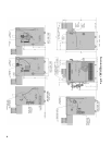
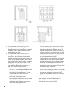
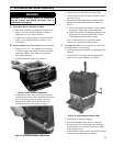
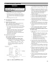
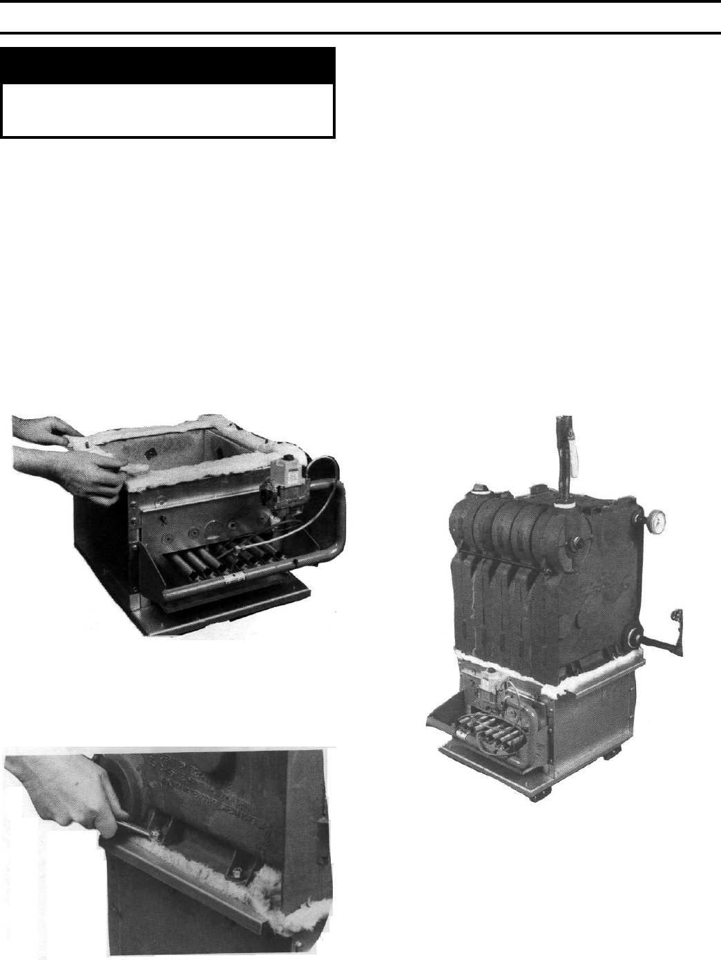
Figure 4: Base Gasket Installation
II. Knocked-Down Boiler Assembly
WARNING
Installation of this boiler should be undertaken
only by trained and skilled personnel from a
qualied service agency.
A. Install Base-Burner-Manifold Assembly
1. Base-Burner-Manifold is shipped assembled from
factory (Gas Valve and Pilot/Burner Assembly is
shipped in the "Gas Controls Carton").
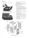
2. Unpack base assembly and place in location where
boiler is to be installed (Refer to Section I: Pre-
Installation).
B. Install assembled cast iron sections on base assembly:
1. Install (4) 5/16" x ¼" self-tapping screws through
(4) holes in upper base ange with screw heads on
underside of ange. Note: Screws are located in
ber gasket parts bag.
2. Install ceramic ber gasket. See Figure 4.
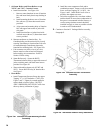
3. Position boiler above base with lugs cast in boiler
sections centered over screws protruding from top of
base. Lower boiler onto base taking care not to
disturb ceramic ber gasket. Secure with 5/16"
locknuts and washers provided. See Figure 5.
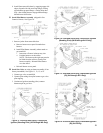
Figure 5: Section Assembly Attachment
4. Loosen nuts on tie rods until only nger tight.
5. If Steam boiler or Water boiler less tankless heater,
proceed to Step C.
6. Water Boiler with tankless heater. Remove heater
opening cover plate and install tankless heater as
follows:
a. Place rubber gasket over heater coil and against
heater plate. Align holes in plate and gasket.
b. Install water heater coil through opening into top
nipple ports of boiler and fasten with 3/8" hex
head machine screws and at washers.
Note: If tankless heater is not installed, heater
opening cover plate must remain in place.
C. Test boiler for leaks before connecting to system and
installing controls, trim and jacket.
1. Attach pressure gauge (capable of indicating 30 psi)
on boiler.
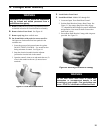
2. Attach ll valve and piping to return tapping and
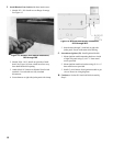
purge valve to supply tapping. See Figure 6.
Figure 6: Hydrostatic Pressure Test
3. Install plugs in remaining tappings.
4. Fill boiler completely with water by venting air
through purge valve. Close purge valve and apply
water pressure of at least 10 psi but not exceeding
30 psi gauge pressure.
5. Examine boiler carefully inside and outside for leaks
or damage due to shipment or handling.