


58
2. Adjust thermostat to highest setting.
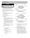
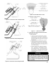
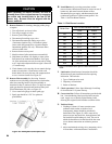
3. Check main burner ames. See Figure 56 or 57.
Flame should have clearly dened inner cones with
no yellow tipping. Orange-yellow streaks caused by
dust should not be confused with true yellow
tipping.
4. Adjust thermostat to normal setting.
G. Check thermostat operation. Raise and lower
temperature setting to start and stop boiler operation.
H. Check ignition system shutoff. Gas valve should close
and pilot and main burners extinguish.
1. Continuous Ignition (Standing Pilot): disconnect
thermocouple from gas valve.
2. Electronic Ignition (EI): disconnect igniter/sensor
cable from ignition module terminal "9".
I. Check low water cutoff (steam only).
1. Adjust thermostat to highest setting.
2. With boiler operating, open drain and slowly drain
boiler.
CAUTION
Do not drain below gauge glass.
3. Main burners will extinguish when water level drops
below low water cutoff. Water should still be visible
in gauge glass. Verify limit, thermostat or other
controls have not shut off boiler.
4. Adjust thermostat to lowest setting. Rell boiler to
normal water line.
J. Check Limit.
1. Adjust thermostat to highest setting.
2. Steam: Observe pressure gauge. When pressure is
indicated, adjust limit to setting below observed
pressure. Main burners should extinguish.
WARNING
Failure to properly adjust gas input rate will result
in over ring or under ring of the appliance.
Improper and unsafe boiler operation may result.
3. Water: Observe temperature gauge. When
temperature exceeds limit set point main burners
should extinguish.
4. Adjust limit to setting above observed reading. Main
burners should reignite.
5. Adjust thermostat to lowest setting. Adjust limit to
desired setting.
K. Adjust gas input rate to boiler. Natural Gas.
1. Adjust thermostat to highest setting.
2. Check manifold gas pressure. Manifold pressure is
listed on Rating Label.
a. Models IN3-IN12 with Standing Pilot, IN3-IN9
with Hot Surface to Pilot and IN3-IN11 with
Electronic Ignition. Adjust gas valve pressure
regulator as necessary (turn adjustment screw
counterclockwise to decrease manifold pressure,
or clockwise to increase manifold pressure). If
pressure can not be attained, check gas valve
inlet pressure. If less than minimum gas supply
pressure listed on Rating Label, contact gas
supplier for assistance.
b. Model IN12 with Electronic Only.
i. Turn off gas valve not having pilot control.
ii. On gas valve with pilot control, adjust gas
valve pressure regulator to obtain required
manifold pressure, or if unattainable, highest
pressure without forcing adjustment screw
(turn adjustment screw counterclockwise to
decrease manifold pressure, or clockwise to
increase manifold pressure).
iii. Turn on gas valve not having pilot control.
Adjust gas valve pressure regulator to obtain
required manifold pressure. Manifold
pressure may not change during initial turns
of adjustment screw.
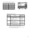
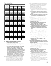
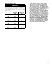
3. Clock gas meter for at least 30 seconds. Use Table
10 to determine gas ow rate in Cubic Feet per
Hour.
4. Determine Input Rate. Multiply gas ow rate by gas
heating value.
5. Compare measured input rate to input rate stated on
Rating Label.
a. Boiler must not be overred. Reduce input rate
by decreasing manifold pressure. Do not reduce
more than 0.3 inch w.c. If boiler is still overred,
contact your Governale distributor or Regional
Ofce for replacement Gas Orice.
b. Increase input rate if less than 98% of Rating
Label input. Increase manifold gas pressure no
more than 0.3 inch w.c. If measured input rate is
still less than 98% of rated input:
i. Remove Main Burners per procedure in
Section X: Service Instructions.
ii. Remove gas orices. Drill one (1) drill size
larger (drill size is stamped on orice).
iii. Reinstall gas orices and main burners.
Measure input rate.
6. Recheck Main Burner Flame.
7. Return other gas-red appliances to previous
conditions of use.