


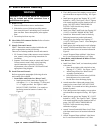
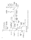
11
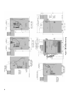
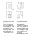
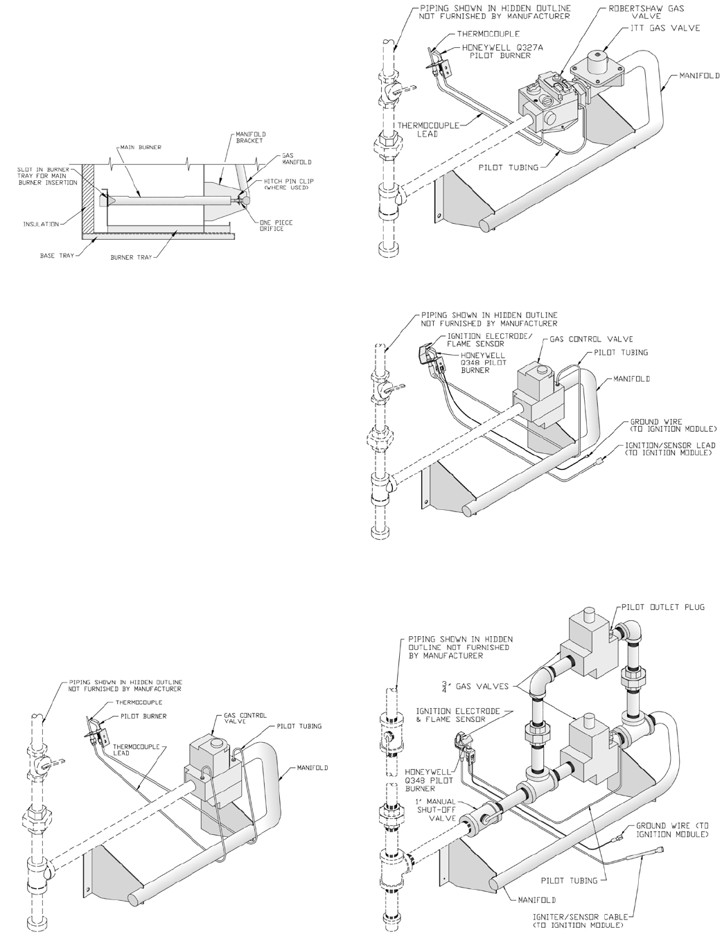
Figure 11: Pilot and Gas Piping, Continuous
Ignition (Standing Pilot) (IN3 through IN9 Only)
Figure 13: Pilot and Gas Piping, Intermittent Ignition
(EI) (IN3 through IN11 Only)
Figure 12: Pilot and Gas Piping, Continuous Ignition
(Standing Pilot) (IN10 through IN12 Only)
Figure 14: Pilot and Gas Piping, Intermittent Ignition
(EI) (IN12 Only)
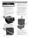
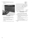
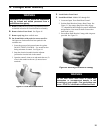
9. Install front removable door by engaging upper side
edges of panel with side receiving anges, sliding
up and under top panel ange - seating front door
fully - then sliding down to engage bottom ange
behind lower front tie bar.
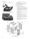
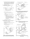
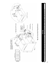
G. Install Pilot/Burner Assembly (shipped in Gas
Controls Carton). See Figure 10.
Figure 10: Combustion Chamber
1. Remove jacket front removable door.
a. Remove burner access panel located above
burners.
b. Install Pilot/Burner Assembly where noted on
gas manifold.
i. Insert rear of burner in burner tray slot.
ii. Position burner over the orice.
NOTE: The burner to the right may need to
be lifted from the orice to install pilot/
burner assembly. Reinstall lifted burner
over the orice.
c. Reinstall burner access panel.
H. Install Gas Valve on main gas burner assembly (if not
factory assembled). See Figure 11, 12, 13, or 14.
1. Connect gas valve to manifold.
2. Connect pilot tubing from pilot burner to gas valve
pilot tapping.
3. Continuous Ignition (standing pilot): connect
thermocouple to gas valve.