


15
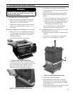
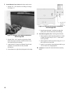
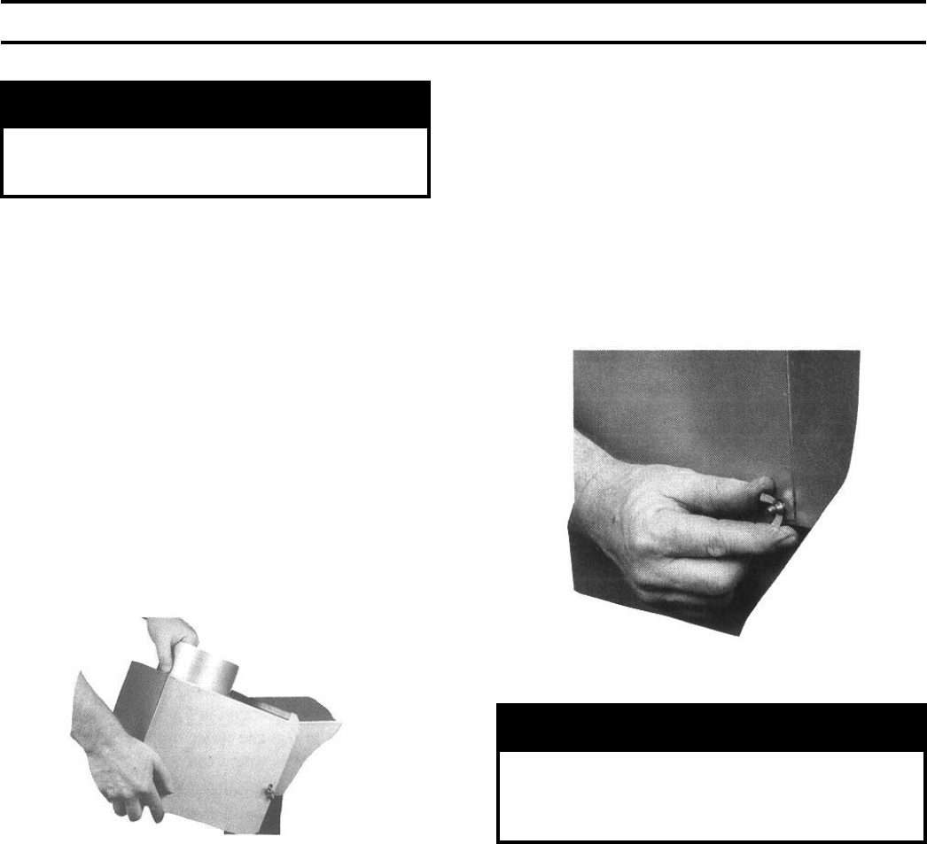
Figure 22: Securing Draft Hood to Canopy
A. Remove crate and move boiler to permanent position
as detailed in Section III: Semi-Pak Boiler Assembly.
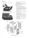
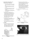
B. Remove Jacket Front Panel. See Figure 45.
C. Remove poly bag from vestibule area.
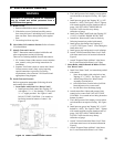
D. On Steam Boilers with probe low water cutoff the
L404 pressure limit/control has been packed in the
vestibule area.
1. Screw the pressure limit/control onto the syphon.
DO NOT TWIST CONTROL. Use wrench on hex
tting at bottom of control. See Figure 18.
2. Snap the electrical conduit from the adjacent
junction box into the hole in the control.
3. Open the control's clear cover and attach the two (2)
wires in the conduit to the two (2) unused screw
terminals.
IV. Packaged Boiler Assembly
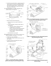
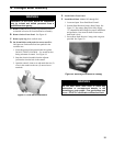
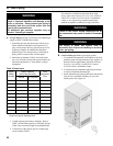
Figure 21: Draft Hood Attachment
E. Install Jacket Front Panel.
F. Install Draft Hood. Models IN3 through IN9.
1. Locate and open "Rear Draft Hood Carton".
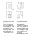
2. Position Draft Hood on Canopy Rear Flange. See
Figure 21. Top canopy ange must fully engage
"U"-shaped draft hood ange for proper installation
and operation. Care must be taken to assure that
draft hood is level.
3. Secure Rear Draft Hood to Canopy with wing nuts
provided. See Figure 22.
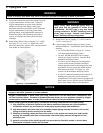
WARNING
Installation of this boiler should be undertaken
only by trained and skilled personnel from a
qualied service agency.
WARNING
Do not alter boiler draft hood or place any
obstruction or non-approved damper in the
breeching or vent system. Flue gas spillage can
occur. ETL/ETLC certication will become void.