


64
CAUTION
When necessary to remove burners, be sure to
reinstall them in the original manner by engaging
the orice and locating hole in the rear of the
burner tray. Burners must be aligned with the
burner manifold.
F. Remove Burners for cleaning, changing orice plugs,
or repairs.
1. Turn off electric service to boiler.
2. Turn off gas supply to boiler.
3. Remove jacket front panel.
4. Disconnect pilot tubing at gas valve.
5. Disconnect thermocouple tubing at gas valve
(Continuous Ignition only). Disconnect igniter/
sensor cable and ground wire at ignition module
Intermittent Ignition (EI) only. Disconnect ame
roll-out switch wires.
6. Remove burner access panel.
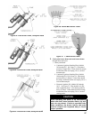
7. Mark location of pilot main burner on manifold.
8. Hold burner on throat. Lift slightly to clear orice.
Pull burner from combustion chamber. See Figure
10. Pilot main burner can only be removed by lifting
at 45° angle after adjacent burner to right is removed
(1" burners only).
9. Check burners to be sure they do not contain foreign
matter or restrictions. Clean burners with a soft
bristle brush, blow any dirt out with compressed air
or use a vacuum cleaner. See Figure 58.
G. Remove Pilot Assembly for Servicing. Remove
machine screw(s) holding pilot burner to pilot bracket,
after rst removing burner with pilot assembly as
described in Step F, number 8 above. To adjust or check
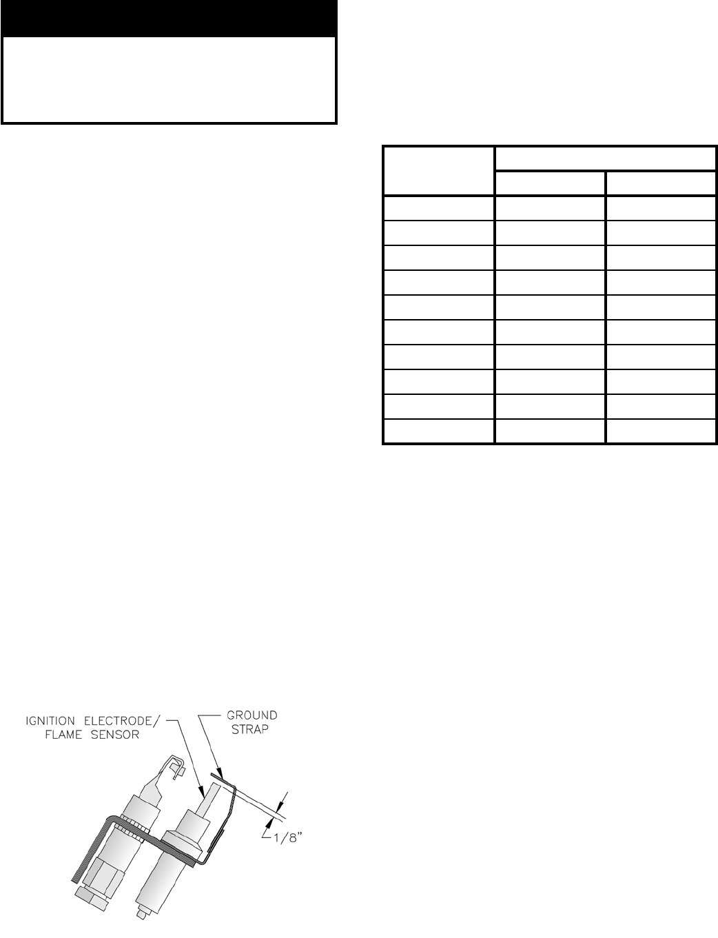
spark gap between electrode and hood on Honeywell
Q348 intermittent (EI) pilot, see Figure 59.
l. Use a round wire gauge to check spark gap.
2. Spark gap should be 0.125" for optimum
performance.
Figure 59: Honeywell Q348 Spark Gap
H. Install Burners by reversing procedures used to
remove burner. Main burners must be in slots in rear of
burner tray and seated on main burner orices.
Reconnect pilot gas supply, and thermocouple lead
(continuous ignition) or igniter/sensor/ground. See
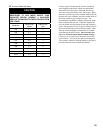
Table 11 for Pilot Burner location.
Table 11: Pilot Burner Location
I. Lubrication. Manufacturers Instruction should be
followed on all parts installed on boiler requiring
lubrication. This includes:
1. Type of lubricant to be used.
2. Frequency of lubrication.
3. Points to lubricate.
J. Check operation. Follow Steps B through L and Step
O from Section IX: System Start-up.
K. Conversion Kits. Follow all instructions provided with
kits. Note that Rating Label provided in kit must be
used. Apply over or beside original Rating Label
allowing the original Serial Number to remain visible.
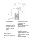
L. Tankless Heater.
1. Flushing of Heater. All water contains some
sediment which settles on inside of coil.
Consequently, heater should be periodically
backwashed. See Figure 28. Allow water at city
pressure to run into hosebib A, through heater, and
out hosebib B until discharge is clear. The tees in
which the hosebibs are located should be the same
size as heater connections to minimize pressure
drop.
2. Adjust and maintain mixing valve (tempering valve)
in accordance with manufacturer's instructions.
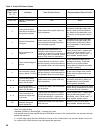
Boiler Size
Pilot Located Between Burners*
1 inch 40mm
IN3 1 & 2 1 & 2
IN4 2 & 3 2 & 3
IN5 3 & 4 2 & 3
IN6 4 & 5 3 & 4
IN7 6 & 7 3 & 4
IN8 7 & 8 4 & 5
IN9 8 & 9 4 & 5
IN10 9 & 10 ---
IN11 11 & 12 ---
IN12 12 & 13 ---
* Burners numbered left to right as viewed from front of
boiler.