


22
VI. Gas Piping
WARNING
Failure to properly pipe gas supply to boiler may
result in improper operation and damage to the
boiler or structure. Always assure gas piping is
absolutely leak free and of the proper size and
type for the connected load.
An additional gas pressure regulator may be
needed. Consult gas supplier.
A. Size gas Piping. Design system to provide adequate gas
supply to boiler. Consider these factors:
1. Allowable pressure drop from point of delivery to
boiler. Maximum allowable system pressure is ½
psig. Actual point of delivery pressure may be less;
contact gas supplier for additional information.
Minimum gas valve inlet pressure is indicated on
Rating Label, located on the vestibule panel.
2. Maximum gas demand. Table 2 lists boiler input
rate. Also consider existing and expected future gas
utilization equipment (i.e. water heater, cooking
equipment).
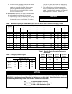
Table 2: Rated Input
For materials or conditions other than those listed
above, refer to the National Fuel Gas Code, NFPA 54/
ANSI Z223.1 and/or CAN/CSA B149.1. Installation
Codes, or size system using standard engineering
methods acceptable to authority having jurisdiction.
WARNING
Failure to use proper thread compounds on all
gas connectors may result in leaks of ammable
gas.
WARNING
Gas supply to boiler and system must be
absolutely shut off prior to installing or servicing
boiler gas piping.
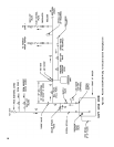
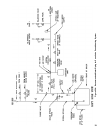
B. Connect boiler gas valve to gas supply system.
1. Use methods and materials in accordance with local
plumbing codes and requirements of gas supplier. In
absence of such requirements, follow the National
Fuel Gas Code, NFPA 54/ANSI Z223.1 and/or
CAN/CSA B149.1 Installation Codes.
2. Use thread (joint) compounds (pipe dope) resistant
to action of liqueed petroleum gas.
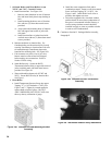
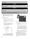
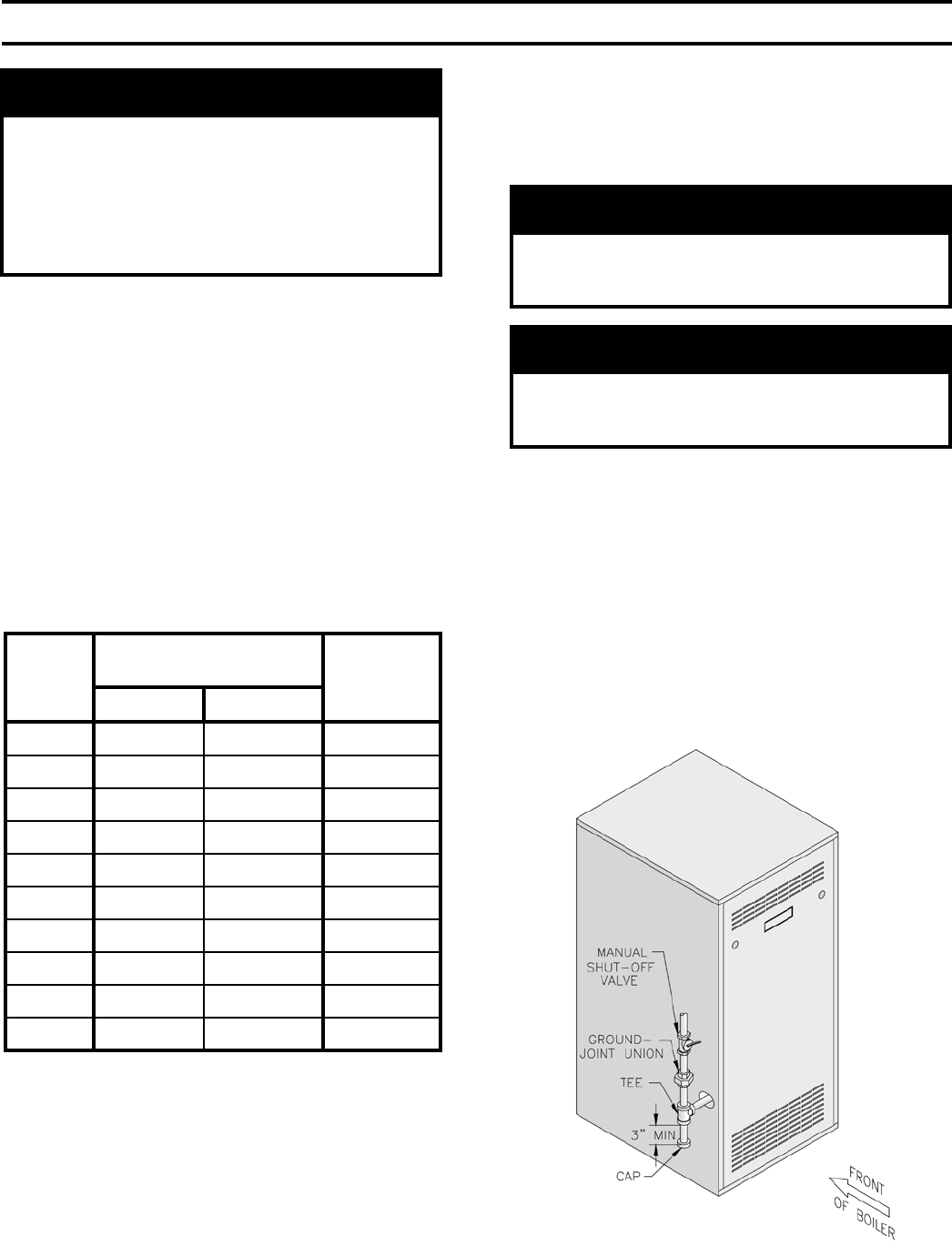
3. Install sediment trap, ground-joint union and manual
shut-off valve upstream of boiler gas valve and
outside jacket. See Figure 29.
3. Length of piping and number of ttings. Refer to
Table 3 for maximum capacity of Schedule 40 pipe.
Table 4 lists equivalent length for standard ttings.
4. Corrections for the specic gravity of natural gas
can be found in Table 5.
Figure 29: Recommended Gas Piping
Boiler
Model
Number
Rated Capacity
[cubic feet per hour]
Gas
Connection
Size
Natural LP/Propane
IN3 62 24¾ ½
IN4 105 42 ½
IN5 140 56 ½
IN6 175 70 ½
IN7 210 84 ¾
IN8 245 98 ¾
IN9 280 112 ¾
IN10 315 126 ¾*
IN11 349 139½ ¾*
IN12 385 154 1
* Gas connection size is 1" on IN10 and IN11
Continuous Ignition (Standing Pilot)