


50
IX. System Start-up
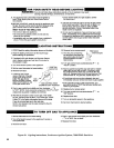
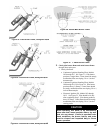
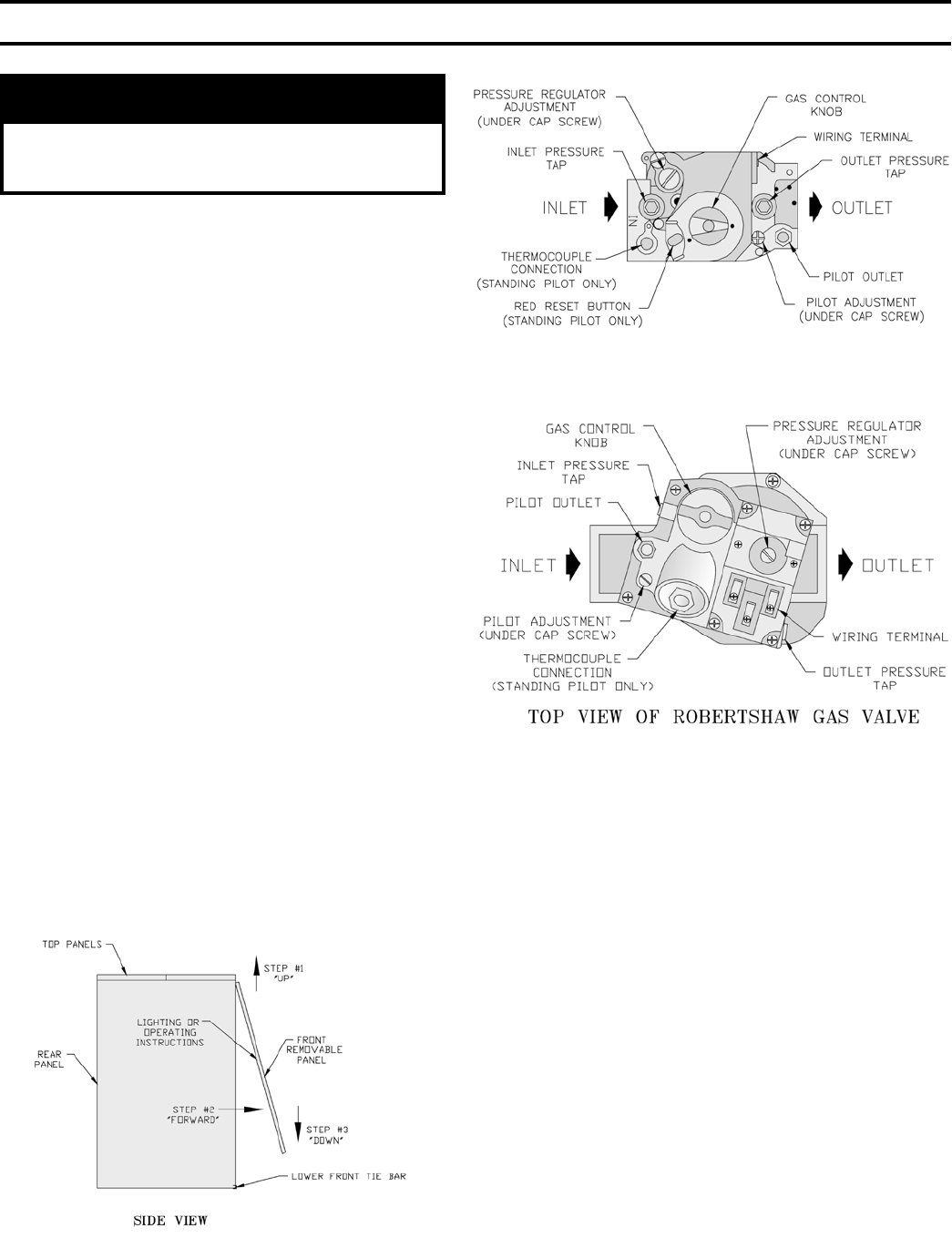
Figure 47: Gas Valve Pressure Tap,
Robertshaw Gas Valve
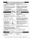
Figure 46: Gas Valve Pressure Tap,
Honeywell Gas Valves
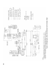
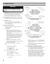
Figure 45: Front Door Removal
WARNING
Completely read, understand and follow all
instructions in this manual before attempting
start up.
A. Safe lighting and other performance criteria were met
with the gas manifold and control assembly provided on
boiler when boiler underwent tests specied in
American National Standard for Gas-Fired Low-
Pressure Steam and Hot Water Boilers, ANSI Z21.13.
B. Check Main Burners. Main burners must be in slots in
rear of burner tray and seated on main burner orices.
C. Fill boiler with water:
1. Steam: ll to normal water line. See Figure 1.
2. Water: ll heating system to approximately 12 PSI.
Vent air from system.
D. Prepare to check operation.
1. Obtain gas heating value (in Btu per cubic foot)
from gas supplier.
2. Adjust limit:
a. Steam: With an L404A1354 - set cut-out
pressure (MAIN scale) on the pressure limit for
(2) PSI and differential pressure (DIFF. scale)
below (2) PSI.
With an L404A1651 or an L404F1367 - set cut-
out pressure (MAIN scale) on the pressure limit
for (1) PSI and differential pressure (DIFF.) for
.5 PSI. These pressures may be varied to suit
individual requirements of the system. See
Figure 18.
b. Water without tankless heater: set at 200°F.
c. Water with tankless heater: set limit at 220°F and
operating control to 200°F.
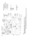
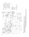
3. Remove front removable panel. See Figure 45.
4. Connect manometer to gas valve pressure tapping
(for IN12 connect to gas valve with pilot control).
See Figure 46 or 47.
5. For natural gas red boiler, temporarily turn off all
other gas-red appliances.
E. Follow Lighting or Operating Instructions.
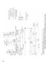
1. To place boiler in operation. See Figure 48, 49, 50
or 51. Sequence of Operation is outlined with
wiring diagrams in Section VIII: Electrical.
2. Electronic Ignition Modules with LED indicators.
Table 7 cross-references the ignition module
terminal designations to the ignition terminal
numbers in the wiring ladder diagrams. The yellow
LED indicates the status of the ame, see Table 8.
The green LED indicates the status of the system,
see Table 9. See Figure 52 for LED locations.