


8
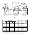
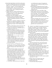
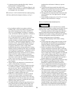
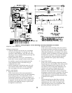
Figure 4: Recommended Piping for Combination
Heating & Cooling (Refrigeration) Systems
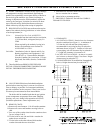
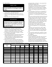
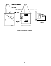
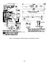
Figure 5
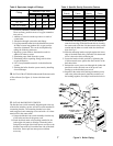
the jacket side panel to secure the power cord to the
jacket.
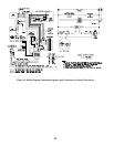
H. Be sure the power cord, mounting bracket, and switch
are secure and located as shown in Figure 6.
Figure 6
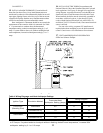
A. The vent damper should be the same size as the outlet
of the Draft Hood. (See Figure 1) Unpack the damper
carefully - DO NOT FORCE IT CLOSED! Forcing the
damper may damage the gear train and void the
warranty. The damper assembly includes a prewired
connection harness for use on all 24V Standing Pilot or
intermittent ignition control systems.
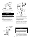
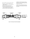
B. Refer to Figure 7 in this manual.
C. Mount the vent damper assembly on the draft hood
without modification to either. (Refer to instructions
packed with the vent damper for specific instructions).
This is a must for the wiring harness to fit and the
damper position indicator to be visible to the users.
12. TO MEET FEDERALLY MANDATED EFFICIENCIES,
THIS BOILER MUST BE EQUIPPED WITH A VENT
DAMPER.
OPEN THE VENT DAMPER CARTON and remove the
Installation Instructions. READ THE INSTALLATION
INSTRUCTIONS THOROUGHLY before proceeding.
The automatic gas control valve supplied on each
Series 2 boiler provides the reduncancy referenced in the
vent damper Installation Instructions.
WARNING
Failure to properly install and use this
Blocked Vent Switch may result in property
damage, personal injury or loss of life.
NOTICE
Please refer to the specifications,
installation instructions and troubleshooting
guide packed in the vent damper carton for
complete detailed installation instructions.
Also refer to Figure 7 in this manual.
D. Install the 90° BX connector attached to the flexible
conduit in the 7/8" knockout on the left side of the
jacket. Plug the factory wired Vent Damper Harness
into the polarized receptacle. Install a cable clamp
around the flexible conduit and attach to the Jacket top
panel. (See Figure 7).