


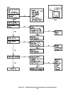

25
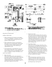
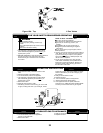
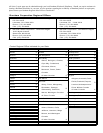
B. Continuous Ignition (Standing Pilot)
Natural gas Models 207 with 40mm (1-9/16") diam-
eter burners and 208 through 210. See Figure 26
LP gas Models 203 through 210. See Figure 26.
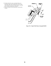
The pilot produces three (3) flames. The center flame
should be steady, medium hard blue enveloping 3/8 to
a 1/2 inch of thermocouple.
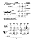
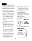
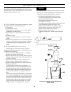
C. Intermittent Ignition
Models 202 with 1" diameter burners and 202X
through 210. See Figure 27.
The pilot produces three (3) flames. The center flame
should be steady, medium hard blue enveloping 3/8 to
a ½ inch of sensing probe.
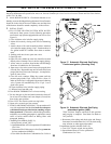
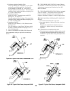
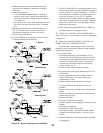
D. Intermittent Ignition
Model 202 with a 40mm (1-9/16") diameter burner.
See Figure 27a.
The pilot produces a single flame. The flame should
be steady, medium hard blue enveloping 3/8 to a ½
inch of sensing probe.
7. CHECK THERMOSTAT OPERATION. Raise and
lower temperature setting as required to start and stop
burners.
8. CHECK HIGH LIMIT CONTROL. Jumper Thermo-
stat Terminals or Thermostat connections in Limit Control.
Allow burners to operate until shutdown by limit. RE-
MOVE JUMPER.
9. CHECK DAMPER OPERATION if Boiler is equipped
with Vent Damper. Vent Damper must be open when
boiler is running. Start boiler, refer to instructions on
damper to determine if damper is in the full open position.
10. CHECK IGNITION SYSTEM SAFETY SHUT-OFF
DEVICE.
A. 24 volt-loosen thermocouple at gas valve.
B. Intermittent Ignition - Remove pilot lead wires from
gas valve.
If burners do not shut down determine cause of
malfunction. Replace necessary items and check
operation.
11. COMBUSTION CHAMBER BURN-OFF
A. The mineral wool combustion chamber panels contain
a cornstarch based binder that must be burned out at
installation to prevent odors during subsequent boiler
operation.
Figure 25: Typical Pilot Flame, Honeywell Q350 Figure 27: Typical Pilot Flame, Honeywell Q3480
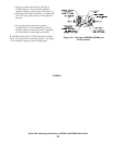
Figure 24: Typical Pilot Flame, Robertshaw 7CL-6
Figure 26: Typical Pilot Flame, Honeywell Q327