


20
SECTION II - OPERATING INSTRUCTIONS
Safe lighting and other performance criteria were met with the gas manifold and control assembly provided on the boiler when
the boiler underwent tests specified in American National Standard for Gas-Fired Low-Pressure Steam and Hot Water Boilers,
ANSI Z21.13b-1994.
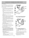
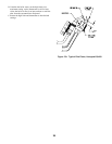
1. MAIN BURNER CHECK - Check main burners to see
that they were not dislodged during shipment. Rear of burners
should be in the slots in the rear of burner tray and the front
of the burners should be seated completely on the orifices.
2. INITIAL START -
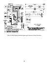
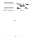
A. FILL ENTIRE HEATING SYSTEM WITH WATER
and vent air from system. Use the following procedure
on a Series Loop System equipped with zone valves. (See
Figure 3).
1.Close isolation valve in boiler supply piping.
2.Isolate all circuits by closing zone valves or balancing
valves.
3.Attach a hose to bib cock located just below isolation
valve in boiler supply piping. (Note - Terminate hose in
five gallon bucket at a suitable floor drain or outdoor
area).
4. Starting with one circuit, open zone valve.
5.Open bib cock.
6.Open fill valve (Make-up water line should be located
directly above isolation valve in boiler supply piping).
7. Allow water to overflow from bucket until discharge
from hose is bubble free for 30 seconds.
8. Open zone valve to the second zone to be purged, then
close the first. Repeat this step until all zones have been
purged, but always have one zone open. At completion,
open all zone valves.
9.Close bib cock, continue filling the system until the
pressure gauge reads 12 psi. Close fill valve. (Note - If
make-up water line is equipped with pressure reducing
valve, system will automatically fill to 12 psi. Leave
globe valve open).
10. Open isolation valve in boiler supply piping.
11. Remove hose from bib cock.
B. Turn ROOM THERMOSTAT to lowest setting.
C. Be sure that gas to pilot and main burners has been off
for at least five minutes and vent damper (if used) has
been in the open position.
D. Turn "OFF" the electric switch serving boiler.
E. Open valve on main gas line at meter.
F. PURGE AIR FROM GAS PIPING. This procedure will
vary with equipment furnished but in all cases adequate
ventilation must be provided and no smoking or open
flame permitted. To determine which of the procedures
outlined in succeeding paragraphs is applicable, match
suffix of boiler model found on Rating Plate with
paragraph heading:
1.Standing Pilot Models (Suffix V):
a. Keep electric switch "OFF".
b. Open Manual Shut-off Valve upstream of Combination
Gas Valve.
c. Disconnect Pilot Tubing at gas valve (Purge must not
be into combustion chamber).
d.Turn Main Gas Knob on Combination Gas Valve to
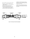
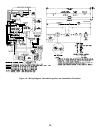
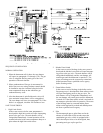
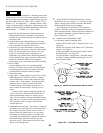
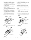
Figure 18: Schematic Pilot and Gas Piping
Intermittent Ignition (HSP)
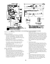
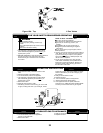
Figure 17: Schematic Pilot and Gas Piping
Continuous Ignition (Standing Pilot)
"Pilot" Position. Depress and hold in this position
until purging is complete. Turn Main Gas Knob to
"off" position.
e. Reconnect pilot tubing and check pipe and fittings
from meter to combination Gas Valve for leaks using
soap solution or other approved method.
2.Intermittent Ignition Models (Suffix S):
a. Turn "ON" electric switch serving boiler.
b.Open Manual Shut-off Valve upstream of
Combination Gas Valve.