


15
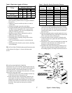
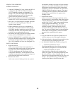
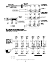
SEQUENCE OF OPERATION
NORMAL OPERATION
1. When the THERMOSTAT calls for heat, the RELAY
is energized. The CIRCULATOR starts and the
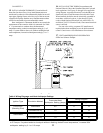
VENT DAMPER is opened (see Paragraphs 17A
through 17D). When the damper blade reaches the
fully open position, the GAS VALVE powers the
igniter circuit and opens the pilot valve.
2. The sensing circuit between the Q3450 or Q3480 pilot
and the GAS VALVE proves presence of pilot flame.*
3. The GAS VALVE de-energizes the igniter and opens
the main valve, allowing main gas to flow and
ignition of main burners.
4. Where condensation of flue gas is encountered in
boiler flues, a REVERSE ACTING CIRCULATOR
CONTROL should be installed to stop the CIRCULA-
TOR before the boiler water temperature drops to that
at which flue gas condensation may occur.
5. The burners and CIRCULATOR will operate simulta-
neously until the THERMOSTAT is satisfied.
6. After the THERMOSTAT is satisfied the main valve,
pilot valve and the circulator will be de-energized and
main burner and pilot flames will be extinguished.
The VENT DAMPER will close (see Paragraph 17E).
SAFETY SHUTDOWN
1. High Limit Switch
In the event excessive boiler water temperature is
developed the High Limit Switch will open, interrupt-
ing power to the VENT DAMPER and the GAS
VALVE. Main Burners and Pilot Burner will be
extinguished immediately. Normal operation will be
resumed when the boiler water temperature drops to a
point where the High Limit Switch closes.
2. Blocked Vent Switch
In the event excessive blockage in the vent system is
developed the blocked vent switch will open interrupt-
ing power to the VENT DAMPER and GAS VALVE.
Main burners and pilot burner will be extinguished
immediately, the VENT DAMPER will close and the
CIRCULATOR will continue to operate. The source
of blockage must be corrected by trained and skilled
personnel from a qualified service agency before
resetting switch.
3. Flame Rollout Switch
In the event excessive blockage in the boiler section
flue passageways is developed the flame rollout switch
will open interrupting power to the VENT DAMPER
and the GAS VALVE. Main burners and pilot burner
will be extinguished immediately. The VENT
DAMPER will close and the CIRCULATOR will
continue to operate. If the flame rollout switch is
activated do not attempt to place the boiler in opera-
tion. The source of blockage must be corrected and the
flame rollout switch replaced by trained and skilled
personnel from a qualified service agency.
4. Pilot
A. Any pilot failure on the Q3450 or Q3480 Pilot will
close the main gas valve and energize the igniter.
B. If the igniter breaks or becomes disconnected, the pilot
valve coil loses power, closing the pilot valve.
5. For TROUBLE SHOOTING GUIDE, see Figure 28.
* · SV9500 and SV9600 Gas Valves:
The igniter and pilot gas valve will stay energized
until either the pilot lights or the call for heat ends.
· SV9501 and SV9601 Gas Valves:
If the pilot fails to light after a 90 second trial for
ignition, the igniter will be de-energized and the pilot
gas valve will close. After a 5 minute delay, the
igniter will be re-energized and the pilot gas valve will
re-open. This continuous retry cycle will end either
when the pilot lights or the call for heat ends.