


24
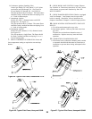
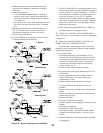
Figure 23: 1 Inch Main Burner Flame
4. CHECK GAS INPUT RATE TO BOILER
USA boilers built for installation at altitudes greater than
2,000 feet above sea level have been specially orificed to
reduce gas input rate 4 percent per 1,000 feet above sea level
per the National Fuel Gas Code, NFPA 54/ANSI Z223.1,
Section 8.1.2 and Appendix F. Canadian boilers' orifice
sizing is indicated on the rating label. High altitude boiler
models are identifiable by the fourth digit after the dash in the
model number. 2: 0-2000', 4 or 5: above 2000'.
A. Input Rate and Maximum Inlet Pressure shown on
Rating Label must not be exceeded. Inlet pressure
must not be lower than minimum inlet pressure shown
on Rating Label.
B. All Rate checks and all adjustments are to be made
while boiler is firing - all other appliances connected
to the same meter as the boiler must be off.
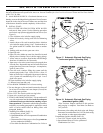
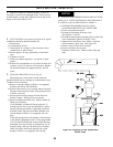
C. With boiler off, water Manometer or water column
gauge should be connected to a shut-off cock installed
in the 1/8" outlet pressure tap in the gas valve (See
Figure 19). By installing gas cock upstream of
manometer, gas pressure can be introduced gradually -
without shut-off cock, surge of pressure when boiler is
turned on, could blow liquid out of manometer.
Replace plug in gas valve when rate check is finished.
D. LP Gas Input:
Adjust Regulator on Gas Valve so that manifold
pressure is 10 inches water column. Turning Regula-
tor Adjusting Screw Clockwise increases pressure.
Counterclockwise rotation decreases pressure.
E. Natural Gas Input
1.Appx. Input - Adjust regulator on Gas Valve so that
manifold pressure is three and a half (3½) inches
water column (three inches water column for high
altitude with 1" main burners). Turning Regulator
Adjusting Screw Clockwise increases pressure,
Counterclockwise rotation decreases pressure. If
more accurate check on input is necessary see (2)
below.
For minor input changes readjust Regulator Gas
Valve to increase or decrease manifold pressure to
obtain corresponding increase or decrease in gas
input. If it is necessary to increase manifold pressure
more than 0.3" of water to obtain rated input, remove
orifices and drill one size larger. Reinstall and
recheck input rate.
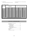
2.Additional Check on Input - Since input is a function
of heating value, specific gravity, and volume of gas
flow contact your utility for the first two items in
order to utilize the formula below. The gas meter
should then be clocked for three (3) minutes with
stop watch and substituting the appropriate values in
the formula below, determine what the gas flow
should be in this 3 minute period to give the input
shown on the Rating Label:
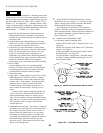
5. MAIN BURNER FLAMES should have a clearly
defined inner cone (see Figure 22 or 23) with no yellow
tipping. Orange-yellow streaks caused by dust should
not be confused with true yellow tipping.
The main burners in this boiler will not operate
cleanly or efficiently if they are contaminated with dirt
and/or construction dust. Burners should be cleaned and
the combustion chamber vacuumed following instruc-
tions in Section III - Service.
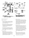
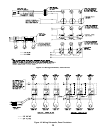
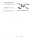
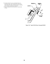
6. CHECK PILOT BURNER FLAME.
A. Continuous Ignition (Standing Pilot)
Models 202 and 202X with 1" diameter burners. See
Figure 24.
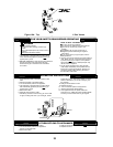
Models 202 and 202X with 40mm (1-9/16") diameter
burners. See Figure 25.
Natural gas Models 203 through 206 and 207 with 1"
diameter burners. See Figure 25.
The pilot produces a single flame. The flame should
be steady, medium hard blue enveloping 3/8 to a 1/2
inch of thermocouple.
Figure 22: 40mm and 50mm Main Burner Flame