


5
per 4,000 Btu per hour input of all equipment in
space. Duct cross-sectional area shall be same as
opening free area.
iii.Horizontal ducts. Minimum free area of 1 square
inch per 2,000 Btu per hour input of all equipment in
space. Duct cross-sectional area shall be same as
opening free area.
g.Ventilation Duct Louvers and Grilles. Equip
outside openings with louvers to prevent entrance
of rain and snow, and screens to prevent entrance of
insects and rodents. Louvers and grilles must be
fixed in open position or interlocked with
equipment to open automatically before burner
operation. Screens must not be smaller than ¼ inch
mesh.
Consider the blocking effect of louvers, grilles and
screens when calculating the opening size to
provide the required free area. If free area of louver
or grille is not known, assume wood louvers have
20-25 percent free area and metal louvers and
grilles have 60-75 percent free area.
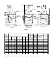
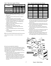
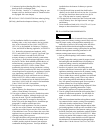
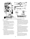
8. CONNECT GAS SERVICE from Meter to gas control
assembly in accordance with Local Piping Codes and
requirements of Gas Company, see Figure 1. They may
require piping of larger size than Control Assembly
Connection, especially if run from meter is long or includes
several elbows. (See Figure 1 for size of Gas Connection to
gas control assembly).
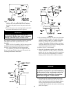
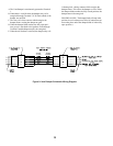
This piping is to be supplied by the installer and must
include a trap, a ground joint union and a manual shutoff
valve upstream of the gas control assembly outside of the
jacket when codes require, see Figure 1. A pipe thread
compound resistant to the action of liquefied petroleum
gases should be applied to all threaded joints in the gas
piping. Pressure testing of the Gas Supply Piping Boiler
and its connections is required before placing the boiler in
operation.
The boiler and shutoff valve must be disconnected
from the gas supply piping system during any pressure
testing at pressures greater than ½ psig.
The boiler must be isolated from the gas supply piping
system by closing its individual manual shutoff valve
during any pressure testing of the gas supply piping system
at pressures equal to or less than ½ psig.
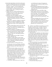
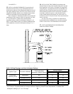
RECOMMENDED SIZING OF GAS SUPPLY
PIPING TO BOILER FOR NATURAL GAS - shall be such
as to provide the required supply of gas without undue loss
of pressure between meter and the boiler. Gas supply piping
should be sized in accordance with the Tables 1, 2 and 3.
The following shall be taken into account:
A. Allowable loss of pressure to assure a burner manifold
pressure of 3½" water.
B. Supply of gas to be provided in cubic feet.
C. Length of piping and number of fittings.
D. Specific gravity of gas.
E. Correction factor for specific gravity.
B. PROVIDE COMBUSTION AND VENTILATION AIR in
accordance with applicable provisions of local building
codes, or: U.S.A. - National Fuel Gas Code, NFPA 54/
ANSI Z223.1, Section 5.3, Air for Combustion and
Ventilation; Canada - Natural Gas Installation Code,
CAN/CGA-B149.1, or Propane Installation Code,
CAN/CGA-B149.2, Part 5, Venting Systems and Air
Supply for Appliances.
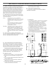
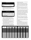
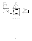
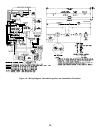
1.CLOSET INSTALLATIONS (confined space) in a
building of other than unusually tight construction
(see definition below), provide combustion and
ventilation air as shown in Figure 2.
2.Installations other than Paragraph (1) above:
a. Determine volume of space (boiler room). Rooms
communicating directly with space (through
openings not furnished with doors) are considered
part of space.
Volume [ft³] = Length [ft] x Width [ft] x Height [ft]
b. Determine Total Input of all appliances in space.
Round result to nearest 1,000 Btu per hour (Btuh).
c. Determine type of space. Divide Volume by Total
Input.
i. If result is greater than or equal to 50 ft³ per 1,000
Btuh, space is considered an unconfined space.
ii.If result is less than 50 ft³ per 1,000 Btuh, space is
considered a confined space.
d.Determine building type. A building of unusually
tight construction has the following characteristics:
i. Walls and ceiling exposed to outside atmosphere
have a continuous water vapor retarder with a
rating of 1 perm or less with openings gasketed
and sealed, and
ii. Weather-stripping has been added on openable
windows and doors, and
iii.Caulking or sealants applied in joints around
window and door frames, between sole plates and
floors, between wall-ceiling joints, between wall
panels, at plumbing and electrical penetrations,
and at other openings.
e. For boiler located in a building of other than
unusually tight construction, adequate combustion
and ventilation air is normally provided by fresh air
infiltration through cracks around windows and
doors.
f. For boiler located in building of unusually tight
construction, provide outdoor air through two
permanent openings which communicate directly or
by duct with the outdoors or spaces (crawl or attic)
freely communicating with the outdoors. Locate one
opening within 12 inches of top of space. Locate
remaining opening within 12 inches of bottom of
space. Minimum dimension of air opening is 3
inches. Size each opening per following:
i. Direct communication with outdoors. Minimum free
area of 1 square inch per 4,000 Btu per hour input of
all equipment in space.
ii. Vertical ducts. Minimum free area of 1 square inch