


4
SECTION I - INSTALLATION INSTRUCTIONS
1. INSPECT SHIPMENT carefully for any signs of damage.
All equipment is carefully manufactured, inspected and
packed. Our responsibility ceases upon delivery of Boiler to
the carrier in good condition. Any claims for damage or
shortage in shipment must be filed immediately against the
carrier by the consignee. No claims for variances or short-
ages will be allowed by Boiler Manufacturer unless pre-
sented within sixty (60) days after receipt of equipment.
2. BOILER INSTALLATION must conform to the require-
ments of the authority having jurisdiction, or in the absence
of such requirements, to:
U.S.A. - National Fuel Gas Code, ANSI Z223.1,
obtainable from the American Gas Association,
1515 Wilson Blvd., Arlington (Rosslyn), VA
22209.
When required by the authority having juris-
diction, the installation must conform to
ANSI/ASME No. CSD-1.
CANADA - "Installation Codes for Natural and LP Gas
Burning Appliances and Equipment, CAN/
CGA-B149.1 or .2-latest edition obtainable
from the Canadian Gas Association, 55 Scars-
dale Road, Don Mills, Ontario, Canada M3B
2R3.
3. These Gas Boilers are DESIGN CERTIFIED FOR
INSTALLATION ON COMBUSTIBLE FLOORING. DO NOT
INSTALL THESE BOILERS ON CARPETING.
4. LOCATE BOILER in front of or behind installation
position before removing Crate. Locate on a level floor as
close to chimney as possible. For basement installations,
provide a solid base such as concrete, if floor is not level or
if water may be encountered on floor around Boiler.
The boiler shall be installed such that the gas ignition
system components are protected from water (dripping,
spraying, rain, etc.) during boiler operation and service
(circulator replacement, control replacement, etc.).
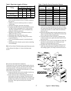
5. REMOVE CRATE-
A. Remove all crate fasteners. Lift off outside container.
B. Remove all screws and brackets securing boiler to
skid.
C. Save two of the wooden slats from the container sleeve
for use in Steps D & E.
D. Tilt the boiler to one side and slide a wooden slat
under the two raised feet.
E. Tilt the boiler to the other side and slide another
wooden slat under the two raised feet.
F. Slide the boiler forward or backward off the skid using
the two wooden slats as runners.
6. Move boiler to permanent position.
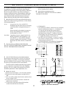
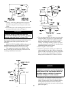
7. PROVIDE CLEARANCE and AIR for COMBUS-
TION and VENTILATION.
A . CLEARANCES
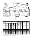
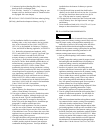
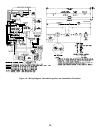
1. ALL INSTALLATIONS - Practical service clearances
must be considered (see Figure 1). A minimum of
24" from the left side and front jacket panels is
recommended for servicing but may be reduced to
minimum shown in Figure 2. Subject to boiler and
system piping, left side clearance may be reduced to
1" if right side clearance is increased to 9".
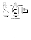
2. ALCOVE INSTALLATIONS - An alcove is consid-
ered a closet as shown in Figure 2 less front. Height
clearance may be reduced to 27".
3. UNCONFINED SPACE (see definition, Paragraph (B)
below) - Height clearance may be reduced to 27".
Figure 2: Minimum Clearances