


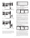


8. Match and connect thermostat wires to proper terminals on
User Interface backplate. See wiring diagram Fig. 12, 13,
and 14.
A — Green = Data A
B — Yellow = Data B
C — White = 24VAC (Com)
D — Red = 24VAC (Hot)
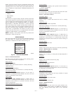
NOTE: It is not mandatory that the above color code be used, but
each ABCD connection in the system MUST be wired consis-
tently. A separate ABCD Connector comes inside packaging and
should be used when connecting to furnace (or fan coil). Ensure
connector is inserted properly into circuit board. (See Fig. 10)
CAUTION: ELECTRICAL OPERATION HAZARD
Failure to follow this caution may result in equipment
damage or improper operation.
Improper wiring of the ABCD connector will cause the
Evolution Zone System to operate improperly. Check to
make sure all wiring is correct before proceeding with
installation or turning on power.
9. Push any excess wire into the wall. Seal hole in wall to
prevent any air leaks. Leaks can affect operation.
10. Attach Evolution Zone Control™ to the mounting plastic by
lining up the plastic guides on the back of the control with
the opening on the mounting plastic and push on.
11. Perform installation of all other system equipment (i.e. zone
sensors, dampers, humidifier, ventilator, UV lights, etc.)
12. Turn on power to equipment.
EQUIPMENT WIRING DIAGRAMS:
See wiring diagrams Fig. 12, 13, and 14 for connecting the
Evolution Zone Control and Smart Sensors to the Damper Control
Module. More information regarding Damper Control set-up and
wiring can be found in Damper Control Module Installation
Instructions.
See wiring diagram Fig. 12 which includes a variable-speed indoor
communicating furnace or FE fan coil, with a 2-speed Puron™
communicating outdoor unit. No additional OAT (outdoor air
temperature) sensor is required because the Evolution Zone
Control will use the temperature sensor inside the 2-speed unit.
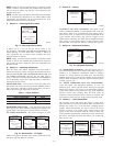
See wiring diagram Fig. 13 for connecting a variable-speed indoor
communicating furnace or FE fan coil with a 1-speed air condi-
tioning unit (non-communicating outdoor). An Outdoor Air Tem-
perature (OAT) sensor may be installed (but is not required) at the
indoor furnace or fan coil OAT terminals. When OAT sensor is
applied, the Evolution System will provide enhanced system
features and benefits.
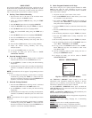
See wiring diagram Fig. 14 for connecting an FE fan coil with a
1-speed heat pump (non-communicating outdoor unit). When OAT
is applied, the Evolution system will provide enhanced system
features and benefits.
NOTE: For other applications not listed, refer to the Network
Interface Module (NIM) Installation Instructions.
HUMIDIFIER CONNECTION — A 24vac bypass or fan
powered humidifier may be installed.
NOTE: Do Not Use a traditional humidistat to control humidifier
operation. If a humidifier is installed, let the Evolution™ Zone
Control operate humidifier.
Bypass Humidifiers — A bypass humidifier should be wired
directly to the furnace or fan coil HUM and 24vac COM terminals.
The Evolution Zone Control will automatically energize the HUM
output during a call for humidification.
Fan Powered Humidifiers — Most fan powered humidifiers
produce internal 24vac in order to energize upon a switch or
contact closure. For this application, a 24vac N.O. Isolation Relay
(DPST) MUST be used to prevent mixing the internal humidifier
power with the indoor equipment transformer. Applying 24vac
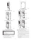
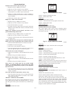
Fig. 8—Large Decorative Backplate
A03188
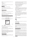
Fig. 9—Decorative Backplate Assembly
A03192
Fig. 10—4–Wire ABCD Connector
A03193
ABCD
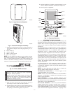
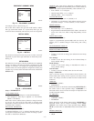
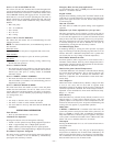
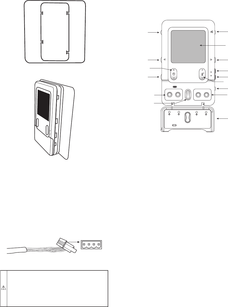
Fig. 11—Functional Overview
A04038
HOLD
COOL
HEAT
SCHEDULE VACATION
PROGRAM
SCROLL
BASIC
ADVANCED
SETUPS
Schedule
to program
temperature
schedule
Vacation
to start/end
vacation
Basic
to set time,
humidity
Advanced
for all other
settings
Scroll
up & down
Fan Button
Display Screen
(LCD)
Right-Side
Button
Heat Button
Cool Button
Temperature
(+/-) Button
System
On/Off Button
Basic & Advanced
Setup Buttons
Flip Down
Door
Left-Side
Button
Zone
Button
Hold
Button
Time (+/-)
Button
Schedule & Vacation
Program Buttons
Up/Down
Scroll Buttons
ZONE
—4—