


Interval at which the Change Humidify Pad notification will be
displayed.
HUMIDIFY WITH FAN:
• NO (default)
• YES
If YES, the humidifier will run with Continuous Fan operation if
there is a humidify demand.
VENTILATOR:
NOTE: Only appears if ventilator is installed.
CLEAN INTERVAL:
• 60 to 180 days of actual operation (default=90)
Interval at which the Clean Ventilator Pre-filter notification will
turn on.
UV LIGHTS INSTALLED:
• NO
• YES
If YES, indicates to the system whether UV lights are installed.
CHANGE INTERVAL:
• 6 to 48 months operation time (default=12 months)
Interval at which the Change UV Lights notification will be
displayed.
Setup = SYSTEM MAINTENANCE
REMIND OWNER OF ROUTINE MAINTENANCE EVERY:
This setup is used to adjust the timer interval in which the normal
System Maintenance notification is turned on for the homeowner.
• Range= OFF, 6 to 24 months, (default=12 months)
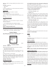
CHECKOUT MENUS
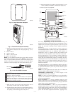
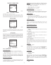
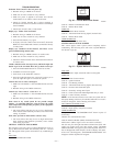
The Checkout menu will show the equipment installed in the
system. A sample checkout menu is shown in Fig. 24.
Checkout = FURNACE
Make sure the furnace is properly installed before continuing.
• LOW HEAT RUNTIME: 5 min.
• HIGH HEAT RUNTIME: 5 min.
This menu item allows the furnace to be exercised. First, a low
heat runtime and high heat runtime are selected. Range=5-120
min.
If only the low heat is to be exercised:
The furnace will execute its ignition start-up sequence. This
sequence will be displayed on the Evolution Zone Control screen.
After the gas valve and blower motor turn on, the screen will
automatically change to ″FURNACE CHECK″ and show the
current operating status of the furnace.
Checkout = FAN COIL
ELECTRIC HEAT CHECK
• ELECTRIC HEAT RUNTIME: 5 min., Default time = 5 min.,
Range=0-120min.
If you have a fan coil with electric heaters, this menu item will
allow the heaters to be exercised.
With self-identifying electric heaters, three stages of electric heat
are available to be exercised in any combination. Non-identifying
heaters will only provide one stage of heat.
Enter the run time (in minutes) of each stage of heat to be
exercised then press START (right-side button). The display will
change to show the fan coil’s operating status.
Checkout = HEAT PUMP HEATING
• HIGH HEAT RUNTIME: 5 min.
• LOW HEAT RUNTIME: 5 min.
• DEFROST: NO
The heat pump heating mode can be exercised with this menu
option. With a 2-speed heat pump, a low heat runtime and a high
heat runtime are independently selectable to exercise. A defrost
cycle is also selectable. Default time = Fixed 5 min. minimum,
range=5-120min.
Checkout = HEAT PUMP COOLING OR AC COOLING
• HIGH COOL RUNTIME: 5 min.
• LOW COOL RUNTIME: 5 min.
The heat pump cooling mode (or AC cooling mode) can be
exercised with this menu option. With a 2-speed heat pump or AC
unit, a low cool runtime and a high cool runtime are independently
selectable to exercise. The display will change to show the heat
pump or AC operating status. Default time = Fixed 5 min.
minimum, range=5-120min.
Checkout = HUMIDIFIER
• OFF
• ON
The humidifier can be exercised On and Off with this menu option.
Checkout = VENTILATOR
SPEED:
• OFF
• LOW
• HIGH
The ventilator can be exercised through all of its operating speeds
with this menu option.
Checkout = ZONING
DUCT ASSESSMENT
This is the same Duct Assessment that runs on first start-up.
Measures duct capacity for each zone. The Duct Assessment will
perform an airflow measurement on each zone and determine the
relative size of each zone along with damper leakage. This
assessment will require approximately 1 minute for each zone in
the system.
NOTE: A Duct Assessment will automatically occur every 24
hours at 1:00 p.m. to check system static and calibrate dampers.
SENSOR DAMPER CHECK:
The Sensor/Damper Check allows the installer to check each zone
damper for operation, as well as insure the zone sensor corre-
sponds to that particular zone.
When first initiated, the Zone 1 damper will fully OPEN, and all
other zones will CLOSE. Using the scroll button, the installer can
select each zone and verify the damper is fully open while all other
dampers remain closed.
After proper damper operation has been verified, the installer can
now check and verify that each remote room sensor corresponds to
the proper zone damper in the same zone. Start from the top and
highlight zone 1 to open damper. Temporarily disconnect any
other zone remote room sensor (at sensor location). That zone
damper will now OPEN, while the Zone 1 damper will close.
EXAMPLE: If the Zone 2 remote room sensor is disconnected, the
Zone 2 damper will now open as indicated on the User Interface
Fig. 24 — CHECKOUT MENUS
A03204
CHECKOUT
FURNACE
HEAT PUMP HEATING
HEAT PUMP COOLING
HUMIDIFIER
ZONING
VENTILATOR
BACK SELECT
—10—