


B. Step 2 — Evolution Zone Control™ Location and
Wiring Considerations
WARNING: ELECTRICAL SHOCK HAZARD
Failure to follow this warning could result in personal
injury or possible equipment damage.
Disconnect Power before routing control wiring.
All wiring must comply with national, local, and state codes.
EVOLUTION™ ZONE CONTROL LOCATION— The Evolu-
tion Zone Control™ User Interface is the command center for the
Evolution Zone System and is typically located in Zone 1 to sense
and control temperature in this zone. It should be located where it
is easily accessible and visible to the adult homeowner or end user.
For accurate temperature measurement, the following guidelines
should be followed:
The Evolution™ Zone Control and Room Sensors should be
mounted:
• Approximately 5 feet (1.5 meters) from the floor.
• Close to or in a frequently used room, preferably on an inside
partitioning wall.
• On a section of wall without pipes or ductwork.
The Evolution™ Zone Control and Room Sensors should NOT be
mounted:
• Close to a window, on an outside wall, or next to a door leading
to the outside.
• Exposed to direct light or heat from a lamp, sun, fireplace, or
other temperature-radiating objects which could cause a false
reading.
• Close to or in direct airflow from supply registers.
• In areas with poor air circulation, such as behind a door or in
an alcove.
REMOTE ROOM SENSOR OPTION — A remote room sensor
can be used with the Evolution™ Zone Control to take the place of
the User Interface internal temperature sensor. This allows the
Evolution™ Zone Control to be mounted in areas with less than
optimal airflow (such as near an exterior door, window or in a
closet). The remote sensor can be wired to the terminal block
connectors labeled S1 and S2 at the User Interface backplate, or
the OS1 and OS1C connection at the Damper Control Module. In
either case, the Evolution Zone Control will automatically detect
the remote room sensor and ignore its internal temperature sensor.
It is also important to note the humidity sensor cannot be remotely
located, so do not locate the Evolution Zone Control in an area
where humidity sensing may not be accurate.
NOTE: S1 & S2 connection on UI backplate is now used for
Remote Room Sensor, NOT for OAT Sensor hookup.
In addition, the Remote Room Sensor is a temperature sensor only,
having no additional user inputs. This sensor is typically connected
to the Damper Control Module and used to sense and control
temperature in each zone.
SMART SENSOR — Any zone may use a Smart Sensor. It
provides a temperature display and buttons to adjust the desired
temperature in that zone only. It also displays outdoor temperature
and indoor humidity. If a Smart Sensor is used in a zone, a Remote
Room Sensor may also be used in the same zone. The Remote
Room Sensor has priority over the Smart Sensor.
WIRING CONSIDERATIONS — Ordinary thermostat wire is
recommended. Use 22 AWG or larger for normal wiring applica-
tions. Continuous wire lengths over 100 ft. should use 20 AWG or
larger.
NOTE: ABCD bus wiring only requires a four-wire connection;
however, it is good practice to run thermostat cable having more
than four wires in the event of a damaged or broken wire during
installation.
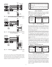
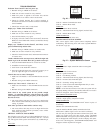
Each communicating device in the Evolution Zone System has a
four-pin connector labeled ABCD. It is recommended that the
following color code be used when wiring each device:
A — Green = Data A
B — Yellow = Data B
C — White = 24VAC (Com)
D — Red = 24VAC (Hot)
It is not mandatory that the above color code be used, but each
ABCD connector in the system MUST be wired consistently.
LOCATING DAMPER CONTROL MODULE — All wiring is
run back to the Damper Control Module. Select a location near the
furnace or fan coil where wiring from the User Interface, each
Remote Room Sensor or Smart Sensor, each damper actuator, and
the equipment itself can come together easily.
The Damper Control Module is approved for indoor use only and
should never be installed with any of its components exposed to
the elements. The Damper Control Module (and zone dampers)
may be installed in any area where the temperature remains
between -4°F. to 158° F. (-20°Cto70°C), and there is no
condensation. The cover must be installed to prevent damage from
other sources. Do not locate where it will be accessible to children.
It may be mounted in either vertical or horizontal position.
Remember that wiring access is likely the most important consid-
eration.
CAUTION: ELECTRICAL OPERATION HAZARD
Failure to follow this caution may result in equipment
damage or improper operation.
To prevent possible damage to the Damper Control
Module, DO NOT mount on plenum, ductwork, or flush
against furnace or fan coil.
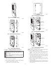
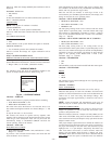
MOUNTING EVOLUTION™ ZONE CONTROL — There are
two options for mounting the Evolution Zone Control™ to the
wall. First, become familiar with all plastic assembly pieces shown
in Fig. 2 through 9. The User Interface will snap together with
either the Recess Mount or the Surface Mount backplate.
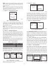
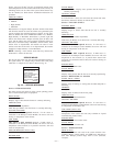
RECESS MOUNT — This provides the thinnest mounting con-
figuration (See Fig. 3). The backplate containing the recessed
terminal block can be mounted directly to the wall by cutting a
hole 1 ½″ wide by 2 1/8″ high. Mark location and cut hole in wall.
NOTE: Always ensure the Evolution Zone Control™ location is
acceptable before cutting any holes in wall.
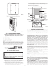
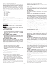
SURFACE MOUNT — This provides surface mounting configu-
ration, which allows use of a small hole in the wall. A surface
mount backplate is supplied (See Fig. 4). Attach backplate as
shown in Fig. 7, and the assembly will mount directly to the wall
requiring only a small hole in the wall allowing a four wire
connection to pass through.
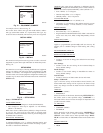
NOTE: Once Evolution Zone Control™ is secured to wall with
the backplate assembly (snapped together), care must be taken not
to bend or break the interlocking tabs when removing. Gently
remove Evolution Zone Control by rocking up/down until inter-
locking tabs release.
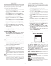
DECORATIVE BACKPLATE — Supplied is a thin decorative
backplate (see Fig. 5), to hide any marks/screw holes left from the
previous thermostat. This decorative backplate (or beauty ring) can
be used in either the recess or surface mount installation by
snapping it onto back of recessed mount backplate or surface
mount backplate before securing to wall. See Fig. 8 and 9 for a
larger decorative backplate P/N SYSTXXOLBP01 (5.75″ wide X
6″ tall), which can be ordered separately.
—2—