


display. The word ″FAIL″ will also be displayed instead of the
actual temperature for Zone 2. Reconnect Zone 2 sensor and try all
remaining sensors one at a time in the system. Smart Sensors may
also be checked, see Smart Sensor Installation Instructions for
procedure.
AIRFLOW LIMITS:
• Low
• Medium
• High (default)
• Maximum
Because there is no bypass damper, the Zone Airflow Limit check
will allow the installer to assess the airflow noise generated by the
system providing the maximum amount of airflow to each zone.
Select 9 ZONE, then select AIRFLOW LIMIT: Low, Medium,
High (default), or Maximum. When Start is pressed (right side
button), the selected zone’s damper will fully open, all others will
close, and the indoor unit will provide the maximum airflow for
that zone (as selected in Setup = ZONING, Airflow Limits). If the
airflow noise is objectionable, the installer can select a lower
airflow noise limit. If the noise is not objectionable, the installer
should leave High selected, or even Maximum.
NOTE: Selecting a lower airflow noise limit may decrease the
homeowner’s comfort in that zone.
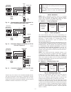
SERVICE MENUS
The Service Info menu will only show the equipment installed in
the system. Below is a sample using a furnace and a heat pump
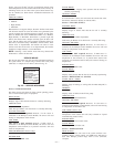
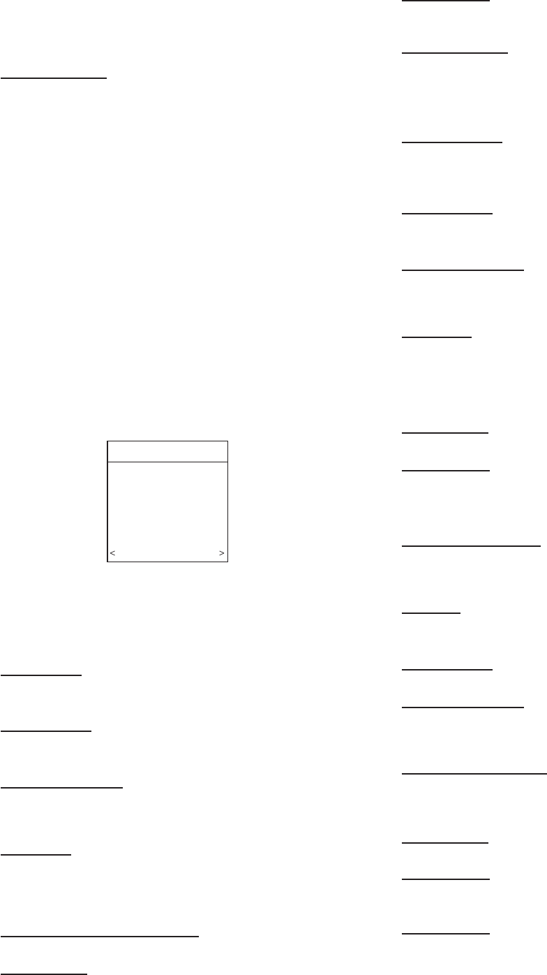
(dual fuel). A sample service menu is shown in Fig. 25.
Service = FURNACE STATUS
The Status screens will show all of the current operating param-
eters of each installed piece of equipment.
HEAT STAGE:
• OFF, LOW, HIGH
Displays stage of heat that the furnace is currently delivering.
AIRFLOW CFM:
• (furnace model dependent)
Cubic Feet per Minute of air the blower is currently delivering.
LEAVING AIR TEMP:
This sensor is NOT required. However, if LAT sensor is
connected to the Damper Control Module, the sensor will read
leaving air temperature of the furnace.
COIL TEMP:
This sensor is NOT required. However, if HPT sensor is
connected to the Damper Control Module, the sensor will read
temperature at that location (i.e. if placed in return-air, will read
return-air temperature).
INDUCER RPM (90% furnaces only):
• Inducer motor RPM value.
BLOWER RPM:
• Blower motor RPM value.
STATIC PRESS:
• Inches of water. Displays static pressure that the furnace is
currently experiencing.
LOCKOUT TIMER:
• Seconds
If a lockout timer is active, this will show the current time value.
See furnace manual for details on lockout timers.
Service = FAN COIL STATUS
ELECTRIC HEAT:
• OFF, LOW, MED, HIGH
Displays stages of electric heat that the fan coil is currently
delivering.
AIRFLOW CFM:
• (fan coil model number dependent)
Cubic Feet per Minute of air the blower is currently delivering.
LEAVING AIR TEMP:
This sensor is NOT required. However, if LAT sensor is
connected to the Damper Control Module, the sensor will read
leaving air temperature of the fan coil.
COIL TEMP:
This sensor is NOT required. However, if HPT sensor is
connected to the Damper Control Module, the sensor will read
temperature at that location (i.e. if placed down stream from
evaporator coil, and before electric heat, will read coil leaving air
temperature).
BLOWER RPM:
• Blower motor RPM value
STATIC PRESS:
• Inches of water
Displays static pressure that the fan coil is currently experiencing.
Service = HEAT PUMP / AC STATUS
STAGE: (HEAT / COOL):
• OFF, LOW, HIGH
Displays stage of heating or cooling that the Heat Pump/AC is
delivering.
DEFROST:
• NO, YES
Displays status of defrost mode if heat pump.
AIRFLOW CFM:
• Indoor unit CFM measurement.
LEAVING AIR TEMP:
This sensor is NOT required. However, if LAT sensor is
connected to the Damper Control Module, sensor will read leaving
air temperature of the indoor unit.
COIL TEMP (outdoor unit):
• Degrees F.
Temperature of the outdoor unit coil (only available on 2-speed
communicating outdoor units).
BLOWER RPM:
• RPM feedback from indoor motor.
STATIC PRESS:
• Static pressure of indoor unit.
Service = ZONING STATUS
ZONE STATUS:
This screen will show each zone in the system with the corre-
sponding damper position (POS), and CFM being delivered to
each zone. Damper position range from 0 to 15 (0=closed,
15=open).
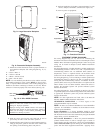
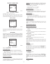
Fig. 25 — SERVICE INFO MENUS
A04092
SERVICE INFO
FURNACE STATUS
HEAT PUMP STATUS
ZONING STATUS
LAST 10 SYSTEM FAULTS
RUN/FAULT HISTORY
TODAY’S DATE
MODEL/SERIAL NUMBER
SERVICE PHONE NUMBER
BACK SELECT
—11—