


NOTE: Install branch circuit disconnect of adequate size per
NEC to handle unit starting current. Locate disconnect within sight
from and readily accessible from unit, per Section 440-14 of NEC.
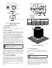
A. ROUTE GROUND AND POWER WIRES
Remove access panel and control box cover to gain access to unit
wiring. Extend wires from disconnect through power wiring hole
provided and into unit control box. Size wires per NEC but not
smaller than minimum wire size shown in Product Data Sheet.
WARNING: The unit cabinet must have as uninter-
rupted or unbroken ground to minimize personal injury if
an electrical fault should occur. The ground may consist
of electrical wire or metal conduit when installed in
accordance with existing electrical codes. Failure to
follow this warning can result in an electric shock, fire, or
death.
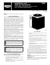
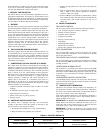
B. CONNECT GROUND AND POWER WIRES
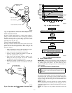
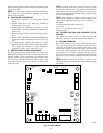
Connect ground wire to ground connection in control box for
safety. Connect power wiring to leads provided as shown in Fig.
12.
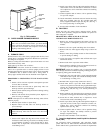
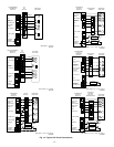
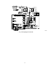
C. CONNECT CONTROL WIRING
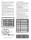
Route 24v control wires through control wiring grommet and
connect to leads provided in control box. (See Fig. 13.)
Use No. 18 AWG color-coded, insulated (35°C minimum) wire. If
thermostat is located more than 100 ft from unit, as measured
along the control voltage wires, use No. 16 AWG color-coded wire
to avoid excessive voltage drop.
All wiring must be NEC Class 1 and must be separated from
incoming power leads.
The outdoor unit requires a minimum of 27va, 24v control power.
D. FINAL WIRING CHECK
IMPORTANT: Check factory wiring and wire connections to
ensure terminations are secured properly. Check wire routing to
ensure wires are not in contact with tubing, sheet metal, etc.
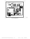
IX. INSTALL ELECTRICAL ACCESSORIES
A. GENERAL
Refer to the individual instructions packaged with kits or acces-
sories when installing. The liquid line solenoid valve accessory is
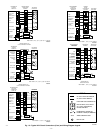
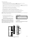
available on these units. See Fig. 14 for wiring diagram.
See Fig. 13 for typical accessory wiring diagrams.
X. MAKE AIRFLOW SELECTIONS
A. AIRFLOW SELECTION FOR 315AAV/315JAV FUR-
NACES
The 315AAV/315JAV Non-Condensing Variable Speed Furnaces
provide high- and low-speed blower operation to match the
capacities of the compressor at high and low speeds. To select the
recommended airflow and for adjustments to the manual switches
labeled SW1, A/C and CF on the control board refer to the furnace
Installation, Start-Up, and Operating Instructions. The
315AAV/315JAV utilizes a control center that allows the install-
ing technician to select the proper airflows. The A/C switch
determines the airflow during high speed compressor operation.
Airflow for high and low speed can be calculated at either 350
CFM per ton or 400 CFM per ton based on the positions of SW1-5.
B. AIRFLOW SELECTION FOR 355MAV FURNACES
The 355MAV Condensing Variable-Speed Furnaces provide high-
and low-speed blower operation to match the capacities of com-
pressor at high and low speeds. To select recommended airflow,
refer to the 355MAV Installation Instructions. The 355MAV
utilizes a control center that allows the installing technician to
select proper airflow. For adjustments to the manual switches
labeled A/C and CF and recommended switch positions, refer to
Furnace Installation Instructions for setting required airflow.
High-speed airflow is determined by the position of the A/C
switches, and low-speed airflow is determined by the position of
the CF switches.
C. AIRFLOW SELECTION FOR FK4 OR FV4 FAN COILS
The FK4 and FV4 provide high- and low-speed blower operation
to match the capacities of compressor at high and low speeds. To
select recommended airflow, refer to the FK4 or FV4 Installation
Instructions. The FK4 and FV4 utilize an EASY SELECT control
board that allows the installing technician to select proper airflow.
The ORANGE SYSTEM TYPE JUMPER wire should be set to
HP–EFF or HP–COMFORT. The BLUE AC/HP SIZE JUMPER
is used to select airflow to match the outdoor unit nominal size in
tons of cooling. The BLACK AC/HP CFM ADJUST jumper is
used to make slight adjustments to the selected airflow tonnage.
See the fan coil Installation Instructions for setting required
airflow. This fan coil has an adjustable blower off delay factory set
at 90 sec for high- and low-speed blower operation.
XI. START-UP
CAUTION: To prevent compressor damage or personal
injury, observe the following:
• Do not overcharge system with refrigerant.
• Do not operate unit in a vacuum or at negative pressure.
• Do not disable low-pressure switch.
CAUTION: To prevent personal injury wear safety
glasses, protective clothing, and gloves when handling
refrigerant and observe the following:
• Back seating service valves are not equipped with
Schrader valves. Fully back seat (counter clockwise)
valve system before removing gage port cap.
CAUTION: Do not vent refrigerant to atmosphere. Re-
cover during system repair or final unit disposal.
Follow these steps to properly start up the system:
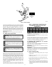
1. The outdoor unit is equipped with a crankcase heater which
operates when the compressor is OFF. Energize crankcase
heater 24 hr before starting unit. To energize heater only, set
indoor thermostat to OFF position and close power discon-
nect to unit.
2. Fully back seat (open) liquid and vapor tube service valves.
3. Unit is shipped with valve stem(s) front seated and caps
installed. Replace stem caps after system is opened to
refrigerant flow (back seated). Replace caps finger tight and
tighten additional 1/12 turn (20 ft-lb torque) with wrench.
Fig. 12—Line Power Connections
A91306
CONTACTOR
DISCONNECT
PER N. E. C. AND/ OR
LOCAL CODES
FIELD POWER
WIRING
FIELD GROUND
WIRING
GROUND
LUG
—7—
→
→