


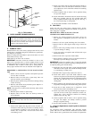
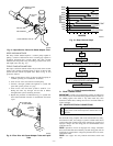
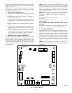
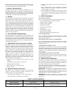

DEEP VACUUM METHOD
The deep vacuum method requires a vacuum pump capable of
pulling a vacuum of 500 microns and a vacuum gage capable of
accurately measuring this vacuum depth. The deep vacuum
method is the most positive way of assuring a system is free of air
and liquid water. (See Fig. 10.)
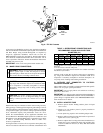
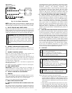
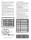
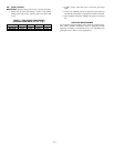
TRIPLE EVACUATION METHOD
The triple evacuation method should only be used when vacuum
pump is only capable of pumping down to 28 in. of mercury and
system does not contain any liquid water. Refer to Fig. 11 and
proceed as follows:
1. Pump system down to 28 in. of mercury and allow pump to
continue operating for an additional 15 minutes.
2. Close service valves and shut off vacuum pump.
3. Connect a nitrogen cylinder and regulator to system and
open until system pressure is 2 psig.
4. Close service valve and allow system to stand for 1 hr.
During this time, dry nitrogen will be able to diffuse
throughout the system, absorbing moisture.
5. Repeat this procedure as indicated in Fig. 11. System will
then contain minimal amounts of contaminants and water
vapor.
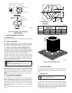
G. FINAL TUBING CHECK
IMPORTANT: Check to be certain factory tubing on both indoor
and outdoor unit has not shifted during shipment. Ensure tubes are
not rubbing against each other or any sheet metal. Pay close
attention to feeder tubes, making sure wire ties on feeder tubes are
secure and tight.
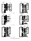
VIII. MAKE ELECTRICAL CONNECTIONS
WARNING: To avoid personal injury or death, do not
supply power to unit with compressor terminal box cover
removed.
Be sure field wiring complies with local and national fire, safety,
and electrical codes, and voltage to system is within limits shown
on unit rating plate. Contact local power company for correction of
improper voltage. See unit rating plate for recommended circuit
protection device.
NOTE: Operation of unit on improper line voltage constitutes
abuse and could affect unit reliability. See unit rating plate. Do not
install unit in system where voltage may fluctuate above or below
permissible limits.
NOTE: Use copper wire only between disconnect switch and
unit.
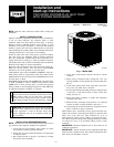
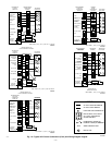
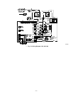
Fig. 8—Liquid Service Valve with Sweat Adapter Tube
A97556
SWEAT/FLARE
ADAPTER
TEFLON
SEAL
PISTON BODY
LIQUID SERVICE VALVE
PISTON
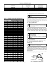
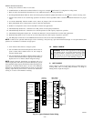
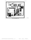
Fig. 9—Filter Drier with Sweat Adapter Tube and Liquid
Tube
A97555
R
-
4
1
0
A
LIQUID
SERVICE
VALVE
LIQUID-LINE
FILTER-DRIER
Fig. 10—Deep Vacuum Graph
A95424
500
MINUTES
01234567
1000
1500
LEAK IN
SYSTEM
VACUUM TIGHT
TOO WET
TIGHT
DRY SYSTEM
2000
MICRONS
2500
3000
3500
4000
4500
5000
A95424
Fig. 11—Triple Evacuation Method
A95425
CHECK FOR TIGHT, DRY SYSTEM
(IF IT HOLDS DEEP VACUUM)
EVACUATE
BREAK VACUUM WITH DRY NITROGEN
WAIT
EVACUATE
CHARGE SYSTEM
BREAK VACUUM WITH DRY NITROGEN
EVACUATE
WAIT
—6—