


NOTE: When two-speed unit is operating in low-capacity cool-
ing, system vapor (suction) pressure will be higher than a standard
single-speed system or high-speed operation. This normal opera-
tion is due to the reduced capacity operating with typically larger
indoor and outdoor coils.
B. ONE MINUTE SPEED CHANGE TIME DELAY
When compressor changes speeds from high to low or low to high,
there is a 1-minute time delay before compressor restarts. The
outdoor fan motor remains running.
C. HEATING OPERATION
This product utilizes a 3-stage heating indoor thermostat. With a
call for first stage heating (Y1), the outdoor fan and low capacity
compressor are energized. If low capacity cannot satisfy heating
demand, high capacity is energized (Y1 and Y2) by the second
stage of the indoor thermostat. Auxiliary or back up heat is
controlled by third stage (W1). After second stage of heat is
satisfied, the unit returns to low capacity operation until first stage
is satisfied or until second stage is required again. When both one
stage and two stage heating are satisfied, the compressor will shut
off. See thermostat Installation Instructions for more staging
information.
NOTE: If unit has not operated within the past 12 hr or following
a unit power-up, upon the next thermostat high- or low-speed
demand, unit operates for a minimum of 5 minutes on high
speed.
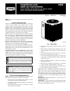
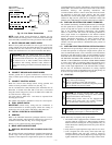
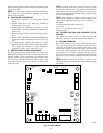
D. STATUS FUNCTION LIGHTS
A system control STATUS function light is located on the outdoor
unit control board. (See Fig. 15). The STATUS light provides
signals for several system operations. See Table 4 for codes and
definitions. Table 4 also provides the order of signal importance.
NOTE: Only one code will be displayed on the outdoor unit
control board (the most recent, with the highest priority).
E. FACTORY DEFAULTS
Factory defaults have been provided in the event of failure of
outdoor air thermistor and/or outdoor coil thermistor. Refer to
Table 6 for default and function.
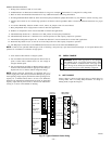
F. COMPRESSOR OPERATION
When the compressor operates in two-capacity operation, the
motor rotates clockwise. Both the lower and upper pistons are
eccentric with the rotating crankshaft, and both compress refrig-
erant. When the compressor operates in single capacity the motor
reverses direction (rotates counterclockwise). The lower piston
becomes idle and the upper piston compresses refrigerant. During
single-capacity operation the “start” and “run” windings are
reversed.
G. CRANKCASE HEATER OPERATION
The two-speed control energizes the compressor crankcase heater
during unit’s off cycle.
H. OUTDOOR FAN MOTOR OPERATION
The two-speed control energizes outdoor fan any time compressor
is operating. The outdoor fan remains energized during the
1-minute speed change time delay and if a pressure switch or
compressor overload should trip. Outdoor fan motor will continue
to operate for one minute after the compressor shuts off when the
outdoor ambient is greater than 100°F.
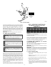
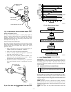
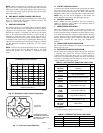
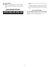
Fig. 16—Resistance Values Versus Temperature
A91431
0
10
20
30
40
50
60
70
80
90
0 20 40 60 80 100 120
TEMPERATURE (DEG. F)
RESISTANCE (KOHMS)
THERMISTOR CURVE
Fig. 17—View from Top of Base Pan
A02218
Control Box
Side of Unit
THERMISTOR PLACED
UNDERNEATH BASE PAN
(ATTACHED TO BASE PAN
WITH ADHESIVE)
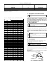
TABLE 4—LED CONTROL FUNCTION LIGHT CODE
CODE DEFINITION *
Constant flash
No pause
No demand
Stand by
10
1 flash
w/pause
Low-speed operation 9
2 flashes
w/pause
High-speed operation 8
3 flashes
w/pause
Outdoor ambient thermistor failure 7
4 flashes
w/pause
Outdoor coil thermistor failure 6
3 flashes
pause
4 flashes
Thermistor out of range† 5
5 flashes
pause
1 flash
Low pressure switch trip 4
5 flashes
w/pause
2 flashes
High pressure switch trip 3
6 flashes
w/pause
Compressor V
C
/V
H
trip 2
Constant light
No pause
No flash
Board failure 1
* Function light signal order of importance in case of multiple signal request; 1
is most important.
† Check both thermistors to determine which is faulty.
TABLE 5—DEFROST DIP SWITCH SETTINGS
TIME DIP SWITCH #1 DIP SWITCH #2
30 up down
60 down up
90 down down
120 up up
—12—