


of the Long-Line Guideline section in the Application Guideline
and Service Manual for Residential Split-System Air Conditioners
and Heat Pumps Using Puron® Refrigerant. If required by
Long-Line Application Guideline, install LSV kit Part No.
KHALS0401LLS specifically designed for Puron® Heat Pumps.
LSV should be installed between filter drier and indoor coil as
close as possible to filter drier. Follow the Installation Instructions
included with accessory kit.
IMPORTANT: Flow arrow must point toward outdoor unit.
VII. MAKE PIPING CONNECTIONS
WARNING: Relieve pressure and recover all refrigerant
before system repair or final unit disposal to avoid
personal injury or death. Use all service ports and open all
flow-control devices, including solenoid valves.
CAUTION: Do not leave system open to atmosphere
any longer than minimum required for installation. POE
oil in compressor is extremely susceptible to moisture
absorption. Always keep ends of tubing sealed during
installation.
CAUTION: To prevent compressor damage DO NOT
bury more than 36 in. of refrigerant tubing. If ANY
tubing is buried, provide 6-in. vertical rise at service
valve.
Outdoor units may be connected to indoor section using accessory
tubing package or field-supplied refrigerant grade tubing of correct
size and condition. Tubing diameters listed in Table 1 are adequate
for equivalent lengths up to 50 ft For tubing requirements beyond
50 ft, substantial capacity and performance losses can occur.
Follow the recommendations in the Application Guideline and
Service Manual for Residential Split-System Air Conditioners and
Heat Pumps Using Puron® Refrigerant to minimize losses. Refer
to Table 1 for field tubing diameters. Refer to Table 2 for
accessory requirements.
If refrigerant tubes or indoor coil are exposed to atmosphere, they
must be evacuated to 500 microns to eliminate contamination and
moisture in the system. Do not leave system open to atmosphere
any longer than minimum required for installation. POE oil in
compressor is extremely susceptible to moisture absorption. Al-
ways keep ends of tubing sealed during installation.
A. OUTDOOR UNIT CONNECTED TO FACTORY-
APPROVED INDOOR UNIT
These outdoor units are carefully evaluated and listed with specific
indoor coils for proper system performance.
IMPORTANT: Do not apply indoor coils which are not factory
approved to these units.
IMPORTANT: For 036 size units matched with the FV/FK005 or
FV/FK006 and the 698BNX048 matched with the FV/FK006, a
piston change is required. Refer to the KHAPX0201BPA Instal-
lation Instructions for details.
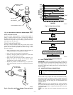
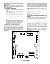
B. INSTALL ADAPTER TUBE
1. Remove plastic retainer holding outdoor piston in liquid
service valve.
2. Check to be sure outdoor piston is properly installed in
liquid service valve.
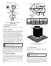
3. Locate plastic bag taped to unit containing adapter tube.
4. Remove Teflon washer from bag and install on open end of
liquid service valve. (See Fig. 8.)
5. Remove adapter tube from bag and connect threaded nut to
liquid service valve. Tighten nut finger tight and then with
wrench an additional 1/2 turn (15 ft-lb). DO NOT OVER
TIGHTEN!
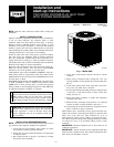
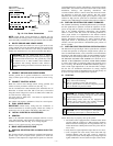
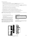
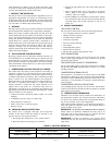
Fig. 6—TXV Kit Contents
A01418
A
B
D
INLET
COIL
E
BULB
INSULATION
TAPE
C
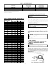
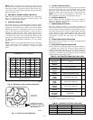
TABLE 1—REFRIGERANT CONNECTIONS AND
RECOMMENDED LIQUID AND VAPOR TUBE
DIAMETERS (IN.)
UNIT LIQUID VAPOR VAPOR (LONG-LINE)
SIZE
Connection
Diameter
Tube
Diameter
Connection
Diameter
Tube
Diameter
Connection
Diameter
Tube
Diameter
024 3/8 3/8 5/8 5/8 5/8 3/4
036 3/8 3/8 3/4 3/4 3/4 7/8
048 3/8 3/8 7/8 7/8 7/8 7/8
060 3/8 3/8 7/8 1-1/8 7/8 1-1/8
Notes:
1. Tube diameters are for lengths up to 50 equivalent ft and/or 20 ft vertical
differential.
2. Do not increase or decrease tubing sizes.
3. If required by local codes, Pressure Guard™ kit is available. See Product
Data Sheet for part numbers.
—4—