


After termination of a defrost cycle, the outdoor fan delays come
on for 20 sec. This allows refrigerant system to recover outdoor
coil heat and minimize the “steam cloud” effect.
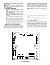
I. DEFROST TIME SELECTION
The defrost interval can be field selected, dependent on local or
geographical requirements. It is factory set at 90 minutes but can
be changed to either 30, 60, or 120 minutes. To select defrost time,
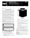
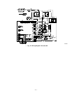
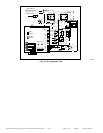
set dip switches located on the left side of the unit board (See Fig.
15). See Table 5 for Defrost Dip Switch Settings.
J. DEFROST
The dual capacity control logic for defrost function is the standard
time and temperature initiated, time or temperature terminated.
Defrost only occurs at outdoor temperatures less than 50°F. The
control initiates defrost when outdoor coil thermistor is 30°F (±2°)
or less, and selected defrost time (interval) has been accumulated
during unit operation. Termination occurs when coil thermistor
reaches 80°F (±5°) or defrost period reaches a maximum of 10
minutes. Defrost will occur at the compressor capacity that is being
called for. During defrost, unit operates in high or low capacity,
energizes reversing valve O and auxiliary heat W2, and de-
energizes outdoor fan. Upon termination, there is a 20-sec delay in
outdoor fan being energized.
K. FIELD-INITIATED FORCED DEFROST
By placing a jumper across forced defrost terminals (See Fig. 15)
for a minimum of 5 sec and then removing it, a defrost cycle can
be initiated. The cycle occurs only if outdoor ambient is less than
50°F, regardless of outdoor coil temperature. The cycle terminates
when coil thermistor reaches 80°F (±5°) or defrost period reaches
a maximum of 10 minutes.
L. COMPRESSOR VOLTAGE FAILURE (6 FLASHES)
The control senses the voltage of the compressor run winding. If
compressor voltage (Vc) is less than 90v when control board is
calling for compressor operation, control shuts compressor off for
15 minutes with outdoor fan running. After 15 minutes (provided
there is a call for Y1 or Y2), control attempts to start compressor.
During this time, a code of 6 flashes appears at control board. If Vc
trip occurs 3 consecutive times during a Y1 request, then low
capacity operation is locked out and control responds to Y2
requests until a reset occurs. If 3 consecutive trips occur in a
combination of Yl and Y2 or all Y2 requests, then both low and
high capacity operation will be locked out. The compressor voltage
failure (6 flashes) can be caused by:
• compressor internal overload trip (refer to Table 7 for correct
winding)
• no 208/230 volt power supply to outdoor unit
• failed compressor contactor(s)
• failure of start relay to pick-up properly.
• improper wiring.
M. PRESSURE SWITCH PROTECTION
The outdoor unit is equipped with high- and low-pressure
switches. If the control senses the opening of the high or low
pressure switch, it will respond as follows:
1. De-energize the compressor hi or low speed contactor,
2. Keep the outdoor fan operating for 15 minutes,
3. Display the appropriate error code on the status light (see
Table 4).
4. After a 15 minute delay, if Yl or Y2 inputs are on and the
LPS or HPS is reset, energize appropriate compressor
contactor, either low or high.
5. If LPS or HPS has not closed after 15 minute delay, outdoor
fan is turned off. If the open switch closes anytime after the
15-minute delay, then resume operation on call for Y1
and/or Y2.
N. MAJOR COMPONENTS
TWO-SPEED CONTROL
The two-speed control board controls the following functions:
• Low- and high-compressor contactor operation
• Outdoor fan motor operation
• Crankcase heater operation
• Compressor protection
• Pressure switch monitoring
• Time delays
• Time/temperature defrost
• Defrost interval selection
• Electric heat operation during defrost mode
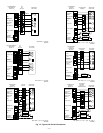
FIELD CONNECTIONS
The two-speed dual capacity control received 24v low-voltage
control system inputs through the screw connections on the left
side of the control board.
TWO-SPEED DUAL CAPACITY COMPRESSOR
The two-speed dual capacity compressor contains motor windings
that provide 3500 RPM operation. Refer to Table 7 for correct
winding resistance.
COMPRESSOR INTERNAL RELIEF
The compressor is protected by an internal pressure relief (IPR)
which relieves discharge gas into compressor shell when differen-
tial between suction and discharge pressures exceeds 525 psi. The
compressor is also protected by an internal overload attached to
motor windings.
COMPRESSOR CONTROL CONTACTORS
Low and High capacity contactor coils are 24 volts. The electronic
control board controls the operation of the low speed (C-L) and the
high speed (C-H) contactors.
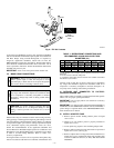
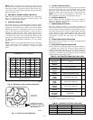
O. TEMPERATURE THERMISTORS
Thermistors are electronic devices which sense temperature. As
the temperature increases, the resistance decreases. Thermistors
are used to sense outdoor ambient and coil temperature. Refer to
Fig. 16 for resistance values versus temperature.
If the outdoor ambient thermistor or coil thermistor should fail, a
fault code appears at electronic control. The crankcase heater is
turned on during all off cycles.
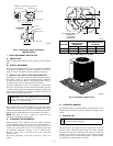
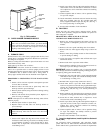
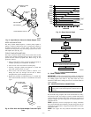
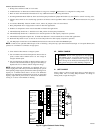
IMPORTANT: OUTDOOR AIR THERMISTOR PLACEMENT
Mount outdoor air thermistor underneath unit base pan lip on
control box side of unit as shown in Fig. 17. Attach to base pan
with adhesive tape or other field expedient means.
IMPORTANT: If outdoor air thermistor is nor properly placed
underneath base pan, unit may have nuisance thermistor out of
range faults.
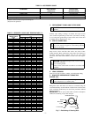
TABLE 6—FACTORY DEFAULTS
FAILED COMPONENT FUNCTION DEFAULT
Ambient Thermistor Defrost Initiation
Defrost is initiated based on coil
temperature and time.
Outdoor Coil Thermistor Defrost Initiation and Termination
Defrost occurs at each time interval, but
terminate after 5 minutes
—13—