


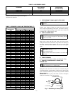

Adjust charge in both heating and cooling by following procedure
shown on charging tables located on pink charging label on back
side of access panel.
NOTE: Unit is to be charged in high capacity only. Charging in
low capacity may cause compressor chattering and possible
damage to the compressor.
B. COOLING ONLY PROCEDURE
1. Operate unit a minimum of 15 minutes before checking
charge.
2. Measure liquid service valve pressure by attaching an
accurate gage to service port.
3. Measure liquid line temperature by attaching an accurate
thermistor type or electronic thermometer to liquid line near
outdoor coil.
4. Refer to charging label for required subcooling tempera-
tures.
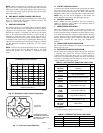
5. Refer to Table 3. Find the point where required subcooling
temperature intersects measured liquid service valve pres-
sure.
6. To obtain required subcooling temperature at a specific
liquid line pressure, add refrigerant if liquid line tempera-
ture is higher than indicated or reclaim refrigerant if
temperature is lower. Allow a tolerance of ± 3°F.
C. HEATING CHECK CHARGE PROCEDURE
To check system operation during heating cycle, refer to the
Heating Pump Charging Instructions on outdoor unit. This chart
indicates whether a correct relationship exists between system
operating pressure and air temperature entering indoor and outdoor
units. If pressure and temperature do not match on chart, system
refrigerant charge may not be correct. Do not use chart to adjust
refrigerant charge.
NOTE: In heating mode, check refrigerant charge only when
pressures are stable. If accessory vapor pressure switch is applied
and operating conditions cause vapor pressure switch and thereby
outdoor fan to cycle, check refrigerant charge in cooling or lower
indoor dry bulb temperature. If in doubt, remove charge and weigh
in correct refrigerant charge.
NOTE: When charging is necessary during heating season,
charge must be weighed in accordance with unit rating plate ±0.6
oz/ft of 3/8-in. liquid line above or below 15 ft respectively.
EXAMPLE:
To calculate additional charge required for a
25-ft line set:
25 ft - 15 ft = 10 ft X 0.6 oz/ft=6ozof
additional charge.
XIII. SYSTEM FUNCTIONS AND SEQUENCE OF OP-
ERATION
The outdoor unit control system has special functions. The
following is an overview of the two-speed control functions:
A. COOLING OPERATION
This product utilizes a 2-stage cooling indoor thermostat. With a
call for first stage cooling (Yl), the outdoor fan and low capacity
compressor are energized. If low capacity cannot satisfy cooling
demand, high capacity is energized (Yl and Y2 or just Y2) by the
second stage of indoor thermostat. After second stage is satisfied,
the unit returns to low-capacity operation until first stage is
satisfied or until second stage is required again. When both one
stage and two stage cooling are satisfied, the compressor will shut
off.
NOTE: Outdoor fan motor will continue to operate for one
minute after compressor shuts off, when outdoor ambient is greater
than 100°F.
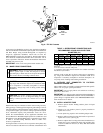
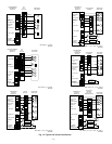
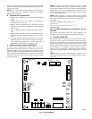
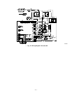
Fig. 15—Control Board
A00379
CEBD430439-03A
SS0ID
PL1 PL2
HP/AC
SEV
RVS
C
HI
LO
PL3
PL4
PL5
OCT OAT HPS LPS
PWM2
PWM1
BRN
BLU
BLK
YEL
RED
CCH L2 ODF VH VC
CESO130078-00
K1
CEPL130439-01
COMM STATUS
D51
D52
A B C D
0
Y2
Y1
W1
C
R
120
30
60
60
30
90
DEFROST
TIME (MIN)
R39
R44
R42
C18
C16
R36
FORCED
DEFROST
1
1
1
S1
R89
R91
R87R86
R85
J1
C31
R61
R65
R38
R33
C2
R9
1 2
—11—