


4. Close electrical disconnects to energize system.
5. Set room thermostat at desired temperature. Be sure the set
point is below indoor ambient and is set low enough to
energize desired speed.
6. Set room thermostat to COOL or HEAT and fan control to
AUTO or ON as desired. Wait for appropriate time delay(s).
Operate unit for 15 minutes. Check refrigerant charge.
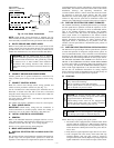
NOTE: Bryant electronic thermostats are equipped with a 15
minute staging timer. This timer prevents the dual capacity system
from operating at high capacity until unit has been operating in low
capacity for 15 minutes unless there is at least a 5°F difference
between room temperature and thermostat set point. To force high
capacity, adjust the set point at least 5° below room ambient for
cooling or 5° above room ambient for heating.
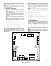
XII. CHECK CHARGE
WARNING: Service valve gage ports are not equipped
with Schrader valves. To prevent personal injury, make
sure gage manifold is connected to the valve gage ports
before moving valves off fully back seated position. Wear
safety glasses and gloves when handling refrigerant.
A. UNIT CHARGE
Factory charge is shown on unit rating plate. To check charge in
cooling mode, refer to Cooling Only Procedure. To charge in
heating mode, weigh the charge in.
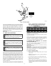
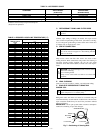
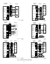
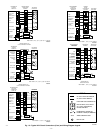
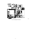
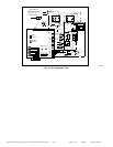
FK4/FV4
FAN COIL
TWO-SPEED
HEAT PUMP
24 VAC HOT
24 VAC COM
FAN
COOL/HEAT
STAGE 2
HEAT STAGE 3
RVS COOLING
N/A
OUTDOOR
SENSOR
CONNECTION
COOL/HEAT
STAGE 1
J2 JUMPER
J1 JUMPER
R
C
G
Y/Y2
W/W2
O/W2
Y1
B
S1
S2
DH
R
G
C
Y/Y2
W1
W2
O
Y1
R
C
Y2
W1
O
Y1
Y1
Y2
Y2
Y1
LLS
A00333
Fig. 14—Typical Solenoid Valve Wiring
WIRING DIAGRAM NOTES:
1. Wiring must conform to NEC or local codes.
2. Underlined letter on thermostat terminal indicates its usage. For example: O/W2 means O is energized in cooling mode.
3. Refer to indoor unit Installation Instructions for any additional features and wiring information.
4. Non-Programmable Model 2S01–B, when used in heat pump installations (jumper R19 NOT cut), uses O/W2 to control reversing valve.
5. Furnace must control its own second-stage operation via furnace control algorithms. Refer to furnace Installation Instructions for proper
setup.
6. To activate dehumidify function on FK4 or FV4, remove J1 jumper at fan coil control board.
7. Heat pump MUST have a high-pressure switch for dual fuel applications.
8. Outdoor air temperature sensor must be attached in all dual fuel applications.
9. Thermidistat Dip Switch No. 1 should be set in ON position for heat pump installations.
10. Thermidistat Dip Switch No. 2 should be set in the ON position for dual capacity compressor operation.
11. Thermidistat Configuration Option No. 10 “Dual Fuel Selection” must be turned ON in all dual fuel applications.
12. Dual Fuel Dip Switch–D (no. 4) must be set in the ON position for dual capacity compressor operation.
13. The DE jumper located next to the DHUM terminal must be removed to enable the DEHUM input.
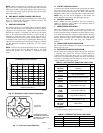
NOTE: If unit has not operated within the past 12 hr or following a unit power-up, upon the next thermostat high- or low-speed demand, unit
operates for a minimum of 5 minutes on high speed.
—10—