


8
c. Inspect all field-- and factory--wiring connections. Be
sure that connections are completed and tight.
d. Ensure wires do not touch refrigerant tubing or sharp
sheet metal edges.
e. Inspect coil fins. If damaged during shipping and
handling, carefully straighten fins with a fin comb.
4. Verify the following conditions:
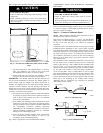
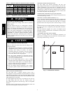
a. Make sure that outdoor--fan blade is correctly positioned
in fan orifice. Top edge of blade should be 3.125 in.(79
mm) down from outdoor coil outlet grille (size
024--048, See Fig. 19) or hub should be 0.708--in. (18
mm) away from motor end bell (size 060, See Fig. 19).
See Outdoor Fan Adjustment section.
b. M ake sure that air filter is in place.
c. Make sure that condensate drain pan and trap are filled
with water to ensure proper drainage.
d. Make sure that all tools and miscellaneous loose parts
have been removed.
START--UP
Step 1 — Check for Refrigerant Leaks
Proceed as follows to locate and repair a refrigerant leak and t o
charge the unit:
1. Locate leak and make sure tha t refrigerant system pressure
has been relieved and reclaimed from both high-- and
low--pressure ports.
2. Repair leak following accepted practices.
NOTE: Install a filter drier whenever the system has been opened
for repair.
Step 2 — Start--Up Cooling and Make Adjust-
ments
Complete the required procedures given in the Pre--Start--Up
section before starting the unit. Do not jumper any safety devices
when operating the unit. Do not operate the unit in cooling mode
when the outdoor temperature is below 40°F(4.4°C) (unless
accessory low--ambient kit is ins talled). Do not rapid cycle the
compressor . Allow 5 min. between “on” cycles to prevent
compressor damage.
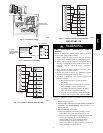
CHECKING COOLING AND HEATING CONTROL
OPERATION
Start and check the unit for proper cooling control operation as
follows:
1. Place room thermostat SYSTEM switch in OFF position.
Observe that blower motor starts when FAN switch is
placed in ON position and shuts down within 60 sec. (for
024--042) or 90 seconds (for 048 and 060) when FAN
switch is placed in AUT O pos ition.
2. Place SYSTEM switch in COOL position and FAN switch
in AUTO position. Set control below room temperature.
Observe that compressor, outdoor fan, and indoor blower
motors start a nd that reversing valve shifts. Observe that
cooling cycle shuts down when control setting is satisfied.
Reve rsing valve (RV) remains energized.
3. Place system switch in HEAT position. Observe that
compressor, indoor fan and outdoor fan energize (Reversing
Valve is deenergized in heat pump heating mode). Set
control above room temperature. Observe that heating cycle
shuts down whe n control setting is satisfied.
4. When using an automatic changeover room thermostat,
place both SYSTEM and FAN switches in AUTO positions.
Observe that unit operates in Cooling mode when
temperature control is set to call for Cooling (below room
temperature), and unit operates in Heating mode when
temperature control is set to call for Heating (above room
temperature).
Step 3 — Refrigerant Charge
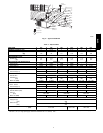
Refrigerant Charge — Amount of refrigerant charge is listed on
unit nameplate and in T able 1. Refer to Bryant Refrigerant Service
Techniques Manual, Refrigerants section. Unit panels must be in
place when unit is operating during charging procedure. Unit must
operate a minimum of 15 minutes before checking charge.
NO CHARGE
Refer to Bryant Refrigerant Service Techniques. Use standard
evacuating techniques. After evacuating system, weigh in the
specified amount of refrigerant (refer to Table 1).
LOW CHARGE COOLING
024--042 units:
1. M easure suction line pressure by attaching a gauge to the
service port.
2. M easure the suction line temperature by attaching a
temperature sensing device to it.
3. Insulate the temperature sensing device so that the outdoor
ambient doesn’t affect the reading.
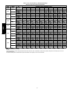
4. Locate the measured suction line pressure in the top row of
Table 5 and the measured outdoor ambient temperature in
the left column of the table. Based on the two values,
determine the required suction line temperature.
5. If the measured suction line temperature is gr eater than the
tabulated temperature, add charge in the system.
048 and 060 units:
1. Measure discharge line pressure by attaching a gauge to the
service port.
2. Measure the liquid line temperature by attaching a
temperature sensing device to it.
3. Insulate the temperature sensing device so that the outdoor
ambient doesn’t affect the reading.
4. Refer to the required subcooling in Tables 3 to find the
required subcooling based on the model size and the
outdoor ambient temperature.
5. Interpolate if the outdoor temperature lies in between the
table values. Extrapolate if the temperature lies beyond the
table range.
6. Find the pressure value corresponding to the measured
pressure on the compressor discharge line.
7. Read across from the pressure reading to obtain the Liquid
line temperature for a required subcooling.
8. Add charge if the measured temperature is higher than the
liquid line temperature va lue in the table.
9. Add charge using the service connection on the suction line
of the compressor.
HEATING MODE CHARGE
Do not attempt to adjust charge by cooling methods while in heat
pump heating mode. Recover refrige rant and weigh in according to
unit data plate refrigerant data.
664B