


2
SAFETY CONSIDERATIONS
Installation and servicing of this equipment can be hazardous due
to mechanical and electrical components. Only trained and
qualified personnel should install, repair, or service this equipment.
Untrained personnel can perform basic maintenance functions such
as cleaning and replacing air filters. All other operations must be
performed by trained service personnel. When working on this
equipment, observe precautions in the literature, on tags, and on
labels attached to or shipped with the unit and other safety
precautions that may apply.
Follow all safety codes. Installation m ust be in compliance with
local and national building codes. Wear safety glasses, protective
clothing, and work gloves. Have fire extinguisher available. Read
these instructions thoroughly and follow all warnings or cautions
included in literature and attached to the unit.
Recognize safety information. This is the safety-- alert symbol
.
When you see this symbol on the unit and in instructions or manu-
als, be alert to the potential for personal injury. Understand these
signal words: DANGER, WARNING, and CAUTION. These
words are used with the safety--alert symbol. DANGER identifies
the most serious hazards which will result in severe personal injury
or death. WARNING signifies hazards which could result in per-
sonal injury or death. CAUTION is used to identify unsafe practic-
es which may result in minor personal injury or product and prop-
erty damage. NOTE is used to highlight suggestions which will
result in enhanced installation, reliability, or operation.
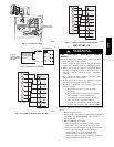
ELECTRICAL SHOCK HAZARD
Failure to follow this warning could result in personal
injury or death.
Before installing or servicing system, always tur n off main
power to system and tag. There may be more than one
disconnect switch. Turn off accessory heater power switch if
applicable.
!
WARNING
CUT HAZARD
Failure to follow this caution may result in personal injury .
Sheet me tal parts may have sharp edges or burrs. Use care
and wear appropriate clothing.
!
CAUTION
INTRODUCTION
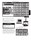
The 664B packaged heat pump is fully self--contained and
designed for outdoor installation (See Fig. 1). Standard units are
shipped in a horizontal-- discharge configuration for installation on
a ground --level slab or directly on the ground if local codes permit.
Standard units can be converted to downflow (vertical) discharge
configurations for rooftop applications with a field supplied
plenum.
RECEIVING AND INSTALLATION
Step 1 — Check Equipment
IDENTIFY UNIT
The unit model number and serial number are printed on the unit
informative plate. Check this information against shipping pape rs.
INSPECT SHIPMENT
Inspect for shipping damage while unit is s till on shipping pallet. If
unit appears to be damaged or is torn loose from its anchorage,
have it examined by transportation inspectors before removal.
Forward claim pape rs directly to transportation company.
Manufacturer is not responsible for any damage incurred in transit.
Check all items against shipping list. Immediately notify the
nearest equipment distribution office if a ny item is missing. To
prevent loss or damage, leave all pa rts in original packages until
installation.
Step 2 — Provide Unit Support
For hurricane tie downs, contact distributor for details and PE
(Professional Engineering) Certificate, if required.
SLAB MOUNT
Place the unit on a solid, level concrete pad that is a minimum of 4
in. (102 mm) thick with 2 in. (51 mm) above grade. The slab
should extend approximately 2 in. (51 mm) beyond the casing on
all 4 sides of the unit. Do not secure the unit to the slab except
when required by local codes.
A 6 --in. (152 mm) wide gravel apron should be used around the
flat surface to prevent airflow blockage by grass or shrubs. The
unit should be level within 1/4 in. (6 mm). This is necessary for the
unit drain to function properly.
GROUND MOUNT
The unit may be installed e ither on a slab or placed directly on the
ground if local codes permit. Place the unit on level ground
prepared with gravel for condensate discharge.
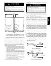
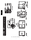
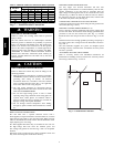
Step 3 — Provide Clearances
The requi red minimum service clearances are shown in Fig. 5.
Adequate ventilation and out door air must be provided.
The outdoor fan draws air through the outdoor coil and discharges
it through the top fan grille. Be sure that the fan dischar ge does not
recirculate to the outdoor coil. Do not locate the unit in either a
corner or under an overhead obstruction. The minimum clearance
under a partial overhang (such as a normal house overhang) is 48
in. (1219 mm) above the unit top. The maximum horizontal
extension of a partial overhang must not exceed 48 in. (1219 mm).
IMPORTANT: Do not restrict outdoor airflow. An air restriction
at either the outdoor-- air inlet or the fan discharge may be
detrimental to compressor life.
Do not place the unit where water, ice, or snow from an overhang
or roof will damage or flood the unit. Do not install the unit on
carpeting or other combustible materials. Slab-- mounted units
should be at least 4 in. (102 mm) above the highest expected water
and runoff levels. Do not use unit if it has been under water.
Step 4 — Place Unit
Unit can be moved with the rigging holds provided in the unit
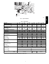
base. Refer to Table 1 for operating weights. Use extreme caution
to prevent damage when moving the unit. Unit must remain in an
upright position during all moving operations. The uni t must be
level with in 1/4 in. (6 mm) for proper condensate drainage; the
ground-- level pad must be level before setting the unit in place.
When a field-- fabricated support is used, be sure that the support is
level and that it properly supports the unit.
Step 5 — Select and Install Ductwork
The design and installation of the duct system must be in
accordance with the standards of the NFPA for installation of
non--residence type air conditioning and ventilating systems,
NFPA 90A or residence type, NFPA 90B and/or local codes and
ordinances.
Select and size ductwork, supply-- air registers, and return air grilles
according to ASHRAE (American Society of Heating,
Refrigeration, and Air Conditioning Engineers) recommendations.
Use the duct flanges provided on the supply-- and return-- air
openings on the side of the unit. See Fig. 5 for connection sizes
and locations. The 14--in. (356 mm) round duct collars are shipped
inside the unit attached to the base pan in the indoor blower
compartment. They are field--installed and must be removed from
the indoor blower compartment prior to start-- up, even if they are
not used for installation.
664B