


18
Only qualified service personnel should perform maintenance and
service procedures that require unit top removal.
Refer to the following top removal procedures:
1. Remove screws on unit top cove r surface. (Save all screws.)
2. Remove screws on unit top cover flange. (Save all screws.)
3. Lift top from unit carefully. Set top on edge and make sur e
that top is supported by unit side that is opposite duct (or
plenum) side.
4. Carefully replace and secure unit top to unit, using screws
removed in Steps 1 and 2, when maintenance and/or service
procedures are completed.
Step 3 — Indoor Blower and Motor
For longer life, operating economy, and continuing efficiency,
clean accumulated dirt and grease from the blower wheel and
motor annually.
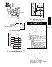
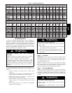
ELECTRICAL SHOCK HAZARD
Failure to follow this warning could result in personal
injury or death.
Disconnect and tag electrical power to the unit before
cleaning and lubricating the blower motor and wheel.
!
WARNING
To clean the blowe r wheel:
1. Remove the blower housing:
a. Remove the screws on the external side of the duct
panel that fasten the housing to the duct panel assembly.
b. Remove the side access panel and uns crew the
mounting bracket that fastens the blower housing to the
internal partition panel fo the control box assembly .
c. Make sure that the blower housing is supported by hand
before completely removing the mounting bracket.
d. Slide the blower housing from the rails of the duct panel
and place it outside the unit.
2. Remove the blower wheel from the housing:
a. Loosen the set screw which secures the wheel to the
motor shaft.
b. Loosen the three mounting legs of the motor by
removing the bolts that fasten themounting legs to the
housing.
c. Slide out the motor assembly (motor, belly band and the
3 mounting legs) from the hub of the wheel.
d. Remove the filler panel at the dischar ge end of the
blower housing by removing the two screws that fasten
it to the housing.
e. Remove the wheel form the housing.
3. Remove the caked on dirt from the wheel and the motor
using a brush.
4. Remove lint and di rt accumulations from the wheel and
housing with a vacuum cleaner, using a soft brush
attachme nt.
5. Remove grease and oil with a mild solvent.
6. Reassemble
a. Slip the wheel back in the housing with the hub set
screw parented in the correct direction.
b. Install the filler panel.
c. Reinsert the motor assembly in the wheel hub and align
the mounting legs with the housing mounting hold
locations.
d. Tighten the mounting bolts to fasten the motor assembly
with the housing.
e. Center the wheel in the housing by sliding it, align the
flat end of the shaft with the set screw and tighten the
set screw .
f. Slide back the blower housing into the mounting rails in
the duct panel and install the mounting bracket back in
its pos ition.
g. Install the screws on the external side of the duct panel
to fasten duct panel with the housing.
h. Replace the side access panel.
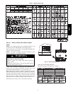
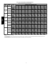
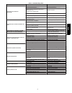
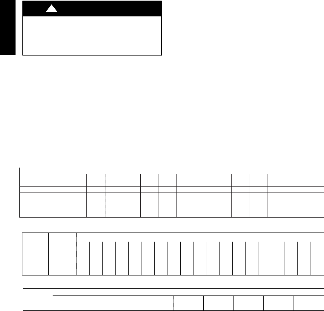
Table 6 – Wet Coil Pressure Drop
UNIT
SIZE
STANDARD CFM (S.C.F.M.)
600 700 800 900 1000 1100 1200 1300 1400 1500 1600 1700 1800 1900 2000
024 .027 .034 040 .047 .053 -- -- -- -- -- -- -- -- -- --
030 -- .036 .042 .050 .055 .063 .072 .081 -- -- -- -- -- -- --
036 -- -- -- .050 .055 .063 .072 .081 .090 .097 -- -- -- -- --
042 -- -- -- -- .042 .049 .052 .059 .065 .071 .078 .085 .091 -- --
048 -- -- -- -- -- -- .072 .081 .090 .097 .108 .120 .129 .139 --
060 -- -- -- -- -- -- -- -- -- .071 .078 .085 .091 .098 .114
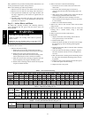
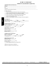
Table 7 – Filter Pressure Drop (in. wc)
UNIT SIZE
FILTER
SIZE in.
(mm)
CFM
500 600 700 800 900 1000 1100 1200 1300 1400 1500 1600 1700 1800 1900 2000 2100 2200 2300
024--036
24 x 24
610 x 610
0.06 0.07 0.08 0.08 0.09 0.09 0.09 0.10 0.11 0.12 0.14 0.15 — — — — — — —
042--060
30 x 30
762 x 762
— — — — — — — — 0.08 0.09 0.10 0.11 0.12 0.13 0.14 0.15 0.16 0.17 0.18
Table 8 – Accessory Electric Heat Pre ssure Drop (in. wc)
HEA TER
kW
CFM
600 800 1000 1200 1400 1600 1800 2000 2200
5--20 0.06 0.08 0.10 0.13 0.15 0.18 0.20 0.23 0.25
664B