


10
Step 5 — Un it Controls
All compressors have the following internal--protection controls.
HIGH--PRESSURE RELIEF VALVE
This va lve opens when the pressure differential between the low
and high side becomes excessive.
LOSS OF CHARGE SWITCH
Located on the outdoor liquid line is a low-- pressure switch which
functions as a loss-- of--charge switch. This switch contains a
Schrader core depressor. This switch opens at 7 psig and closes at
22 psig. No adjustment is necessary.
COMPRESSOR OVERLOAD
This overload interrupts power to the compressor when either the
current or internal temperature become excessive, and
automatically resets when the int ernal temperature drops to a safe
level.
This overload may require up to 60 minutes (or longer) to reset;
therefore, if the internal overload is suspected of being open,
disconnect the e lectrical power to the unit and check the circuit
through the overload with an ohmmeter or continuity tester.
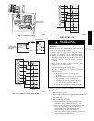
Step 6 — Compressor Rotation
On 3--Phase units it is important to be certain compressor i s
rotating in the proper direction. To determine whether or not
compressor is rotating in the proper direction:
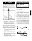
1. Connect service gages to suction and discharge pressure
fittings .
2. Energize the compressor.
3. The suction pressure should drop and the discharge pressure
should rise, as is normal on any start--up.
If the suction pressure does not drop and the discharge pressure
does not rise to normal levels:
1. Turn off power to the unit and tag disconnect.
2. Reverse any two of the unit power leads.
3. Turn on power to the unit.
The suction and discharge pressure levels should now move to
their normal start--up levels.
NOTE: When the compressor is rotating in the wrong direction,
the unit makes an elevated level of noise and does not provide
cooling.
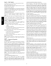
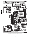
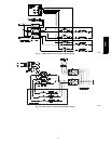
Step 7 — Sequence of Operation
FAN OPERATION
The FAN switch on the thermostat controls indoor fan operation.
When the FAN switch is placed in the ON position, the IFR
(indoor--fan relay) is energized through the G terminal on the
thermostat. The normally--open contacts close, which then provide
power to the indoor (evaporator) fan motor (IFM). The IFM will
run continuously when the FAN switch is set to ON.
When the FAN switch is set to AUT O, the thermostat deener gizes
the IFR (provided there is not a call for cooling). The contacts open
and the IFM is deenergized. The IFM will be energized only when
there is a call for cooling, in heat pump heating mode or if the unit
is equipped with accessory electric heat, the indoor--fan motor will
also run while the accessory electric heat is energized.
NOTE: Some units are equipped with a time--delay relay. On
these units, the indoor fan remains on for 30 seconds after G or Y
is deenergized.
COOLING OPERATION (SIZES 024 --042)
With a call for cooling (Y/Y2), the indoor fan energizes
immediately whereas the contactor energizes after a 5 minute time
delay (in case of initial start--up) starting the compressor and the
outdoor fan motor. When the cooling demand is met, Y/Y2
de--energizes, shutting the compressor, indoor fan and the outdoor
fan.
COOLING OPERATION (SIZES 048 AND 060)
These units utilize a 2 stage indoor thermostat. With a first stage
call for cooling (Y1), the indoor fan (low stage) energizes
immediately whereas the contactor energizes after a 5 minute time
delay (in case of an initial start--up) starting the compressor (low
stage) and the outdoor fan motor. If the low stage operation cannot
satisfy the cooling demand, the second stage cooling (Y2)
energizes switching the compressor into high stage cooling through
energizing an internal solenoid valve inside the scroll compressor
and switching the indoor fan into high stage. When second stage
cooling is satisfied, Y2 de-- energizes switching the compressor and
the indoor fan into low stage cooling. When the low stage cooling
dema nd is met, Y1 de--energizes shutting the compressor, indoor
fan and the outdoor fan.
HEATING OPERATION (SIZES 024 --042)
With a call for heating (Y1), the indoor fan (low stage) energizes
immediately whereas the contactor energizes after a 5 minute time
delay (in case of initial start--up) starting the compressor and the
outdoor fan motor. If Y/Y2 cannot satisfy the heating demand, the
auxiliary or backup heat (W2) energizes. In case of stage d heating,
W3 is energized if the demand is not met. The highest airflow
selected is run while the electric heat is in ope ration. When heating
demand is met, W3, W2 and Y/Y2 sequentially de-- energize
shutting the compressor , indoor fan and the outdoor fan.
HEATING OPERATION (SIZES 048 AND 060)
With a first stage call for heating (Y1), the indoor fan (low stage)
energizes immediately whereas the cont actor energizes after a 5
minute time delay (in case of initial start--up) starting the
compressor (low stage) and the outdoor fan motor. If the low stage
oepration cannot satisfy the heating demand, the second stage
heating (Y2) energizes switching the compressor into high stage
heating through energizing an internal solenoid valve inside the
scroll compressor and switching the indoor fan into high stage. The
auxiliary or backup heat is controlled by a third stage (W2). If the
demand is not met, W3 is energized in case of staged heating.
When heating demand is satisfied, W3, W2 and Y2 sequentially
de-- energize switching the compressor and the indoor fan into low
stage heating. When the low stage heating demand is met, Y1
de--energizes shutting the compressor, indoor fan and the outdoor
fan.
CONTINUOUS FAN
With the continuous Indoor fan option selected on the thermostat,
G is continuously energized. In case of 024--042 units, the selected
airflow setting is provided. In case of 048 and 060 units, t he
system runs low stage (Y1) airflow for continuous fan operation.
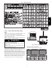
DEFROST
Defrost board (DB) is a time and temperature control, which
includes a field--s electable time period between checks for defrost
(30, 60, 90 and 120 minutes). The time period is factory--set at 60
minutes and should only be adjusted by a trained service person.
Electronic timer and defrost cycle start only when contactor is
energized and defrost thermostat (DFT) is closed.
Defrost mode is identical to Cooling mode. The outdoor fan motor
stops because of “OF1” and “OF2” contacts opening on the defrost
board, a bank of optional electric heat turns on to warm air
supplying the conditione d space.
ELECTRIC RESISTANCE HEATING
If accessory electric heaters are installed, on a call for “Eme rgency
Heat” the thermostat energizes W whi ch energizes the heater relay
and in turn energizes the electric heaters. The IFR is energized
which starts the indoor--fan motor. If the heaters are staged, W2 is
energized when the second stage of heating is required. When the
need for heating is satisfied, the heater and IFM are de--e nergized.
664B