


19
Step 4 — Outdoor Coil, Indoor Coil, and
Condensate Drain Pan
Inspect the condenser coil, evaporator coil, and condensate drain
pan at least once each year.
The coils are easily cleaned when dry; therefore, inspect and clean
the coils either before or after each cooling season. Re move all
obstructions, including weeds and shrubs, that interfere with the
airflow through the condenser coil.
Straighten bent fins with a fin comb. If coated with dirt or lint,
clean the coils with a vacuum cleaner, using the soft brush
attachme nt. Be careful not to be nd the fins. If coated with oil or
grease, clean the coils with a mild detergent and wa ter sol ution.
Rinse coils with clear water, using a garden hose. Be careful not to
splash water on motors, insulation, wiring, or air filter(s). For best
results, spray condenser coil fins from inside to outside the unit. On
units with an outer and inner condenser coil, be sure to clean
between the coils. Be sure to flush all dirt and debris from the unit
base.
Inspect the drain pan and condensate drain line when inspecting
the coils. Clean the drain pan and condensate drain by removing all
foreign matter from the pan. Flush the pan and drain trough with
clear water. Do not splash water on the insulation, motor, wiring, or
air filter(s). If the drain trough is restricted, clear it with a
“plumbers snake” or similar probe device.
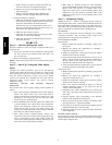
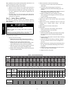
Step 5 — Outdoor Fan
UNIT OPERATION HAZARD
Failure to follow this caution may result in dama ge to unit
components.
Keep the condenser fan free from all obstructions to ensure
proper cooling operation. Never place articles on top of
unit.
CAUTION
!
1. Shut off unit power supply and install lockout tag.
2. Remove outdoor--fan assembly (grille, mot or, motor cover,
and fan) by removing screws and flipping assembly onto
unit top cover.
3. Loosen fan hub setscrews.
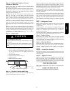
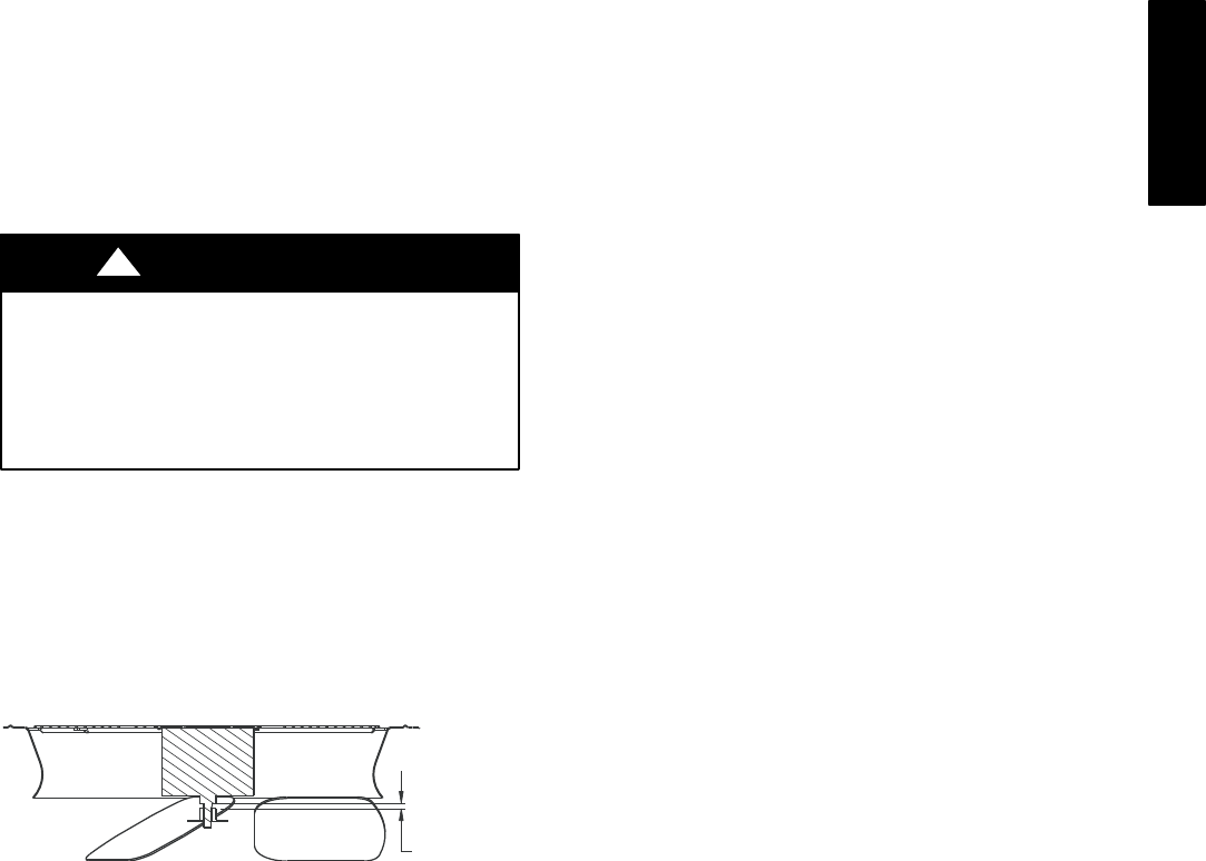
4. Adjust fan height as shown in Fig. 19.
5. Tighten setscrews.
6. Replace outdoor--fan assembly.
15/32-in. (12 mm)
A08004
Fig. 19 -- Outdoor Fan Adjustment
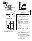
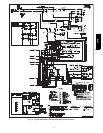
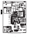
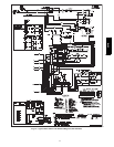
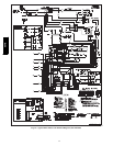
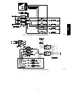
Step 6 — Electrical Controls and Wiring
Inspect and check the electrical controls and wiring annually. Be
sure to turn off the electrical power to the unit.
Remove access panel to locate all the electrical cont rols and wiring.
Check all electrical connections for tightness. Tighten all screw
connections. If any smoky or burned connections are noticed,
disassemble the connection, clean all the parts, re--strip the wire
end and reassemble the connection properly and securely.
Check to ensure no wires are touching refrigerant tubing or sharp
sheet metal edges. Move and secure wires to isolate from tubing
and sheet metal edges.
After inspecting the electrical cont rols and wiring, replace all the
panels. Start the unit, and observe at least one complete cooling
cycle to ensure proper operation. If discrepancies are observed in
operating cycle, or if a suspected malfunction has occurred, check
each electrical component with the proper electrical
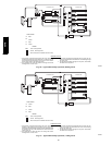
instrumentation. Refer to the unit wiring label when making these
checks.
Step 7 — Refrigerant Circ uit
Inspect all refrigerant tubing connections and the unit base for oil
accumulation annually. Detecting oil generally indicates a
refrigerant leak.
If oi l is detected or if low performance is suspected, leak test all
refrigerant tubing using an electronic leak detector, or liquid-- soap
solution. If a refrige rant leak is detected, refer to Check for
Refrigerant Leaks section.
If no refrigerant leaks are found and low performance is suspected,
refer to Checking and Adjusting Refrigerant Charge section.
Step 8 — Indoor Airflow
The heating and/or cooling airflow does not require checking
unless improper performance is suspected. If a problem exists, be
sure that all supply -- and return-- air grilles are open and free from
obstructions , and that the air filter is clean.
Step 9 — Metering Devices
Refrigerant cooling metering device is an AccuRater (024--042) or
TXV (048 and 060) located upstream of the indoor coil distributor
assembly. Refrigerant heating mode metering device is an
AccuRater located upstrem of the outdoor coil distributor
assembly.
Step 10 — Liquid Line Strainers
The liquid line strainers (to protect metering devices) are made of
wire mesh and are located in the liquid lines on the inlet side of the
metering devices.
Step 11 — High Flow Valves
High flow valves are located on the compressor hot gas and suction
tubes. Large black plastic caps distinguish these valves with
O--rings located inside the caps. These valves can not be accessed
for service in the field. Ensure the plastic caps are in place and tight
or the possibility of refrigerant leakage could occur.
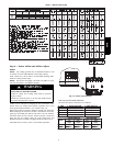
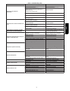
TROUBLESHOOTING
Refer to the Troubleshooting Chart (Table 9) for troubleshooting
information.
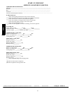
START--UP CHECKLIST
Use the Start--Up Checklist at the back of this manual.
664B