


6
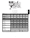
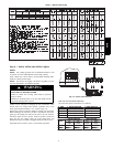
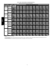
Table 2 – Minimum Airflow for Safe Electric Heater Operation
Unit Size
Minimum Airflow (CFM)
5kW 7.5kW 10kW 15kW 20kW
024 500 650 750 -- --
030 600 800 1050 -- --
036 600 800 1050 1150 1200
042 600 800 1050 1150 1200
048 600 800 1050 1150 1200
060 600 800 1050 1150 1200
Step 7 — Install Electrical Connections
ELECTRICAL SHOCK HAZARD
Failure to follow this warning could result in personal
injury or death.
The unit cabinet must have an uninterrupted, unbroken
electrical ground to minimize the possibility of personal
injury if an electrical fault should occur. This ground may
consist of an electrical wire connected to the unit ground
screw in the control compartment, or conduit approved for
electrical ground when installed in accordance with N EC,
ANSI/NFPA 70 American Nationa l Standards Ins titute/
National Fire Protection Association (latest edition) (in
Canada, Canadian Electrical Code CSA C22.1) and local
electrical codes.
!
WARNING
UNIT COMPONENT DAMAGE HAZARD
Failure to follow this caution may result in dama ge to the
unit being installed.
1. Ma ke all electrical connections in accordance with NEC
ANSI/NFP A 70 (latest edition) and local electrical codes
governing such wiring. In Canada, all electrical
connections must be in accordance with CSA standard
C22.1 Canadian Electrical Code Part 1 and applicable
local codes. Refer to unit wiring diagram.
2. Use only copper conductor for connections between
field-- supplied electrical disconnect switch and unit. DO
NOT USE ALUMINUM WIRE.
3. Be sure that high--voltage power to unit is within
operating voltage range indicated on unit rating plate. On
3--phase units, ensure phases are balanced within 2
percent. Consult local power company for correction of
improper voltage and/or phase imbalance.
4. Do not damage internal components when drilling
through any panel to mount electrical hardware, conduit,
etc.
!
CAUTION
HIGH--VOLTAGE CONNECTIONS
The uni t mus t have a separate electrical service with a
field-- supplied, waterproof disconnect switch mounted at, or within
sight from the unit. Refer to the unit rating plate, NEC and local
codes for maximum fuse/circuit breaker size and minimum circuit
amps (ampacity) for wire sizing.
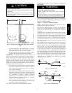
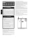
The field--supplied disconnect may be mounted on the unit over
the high-- voltage inlet hole when the standard power and
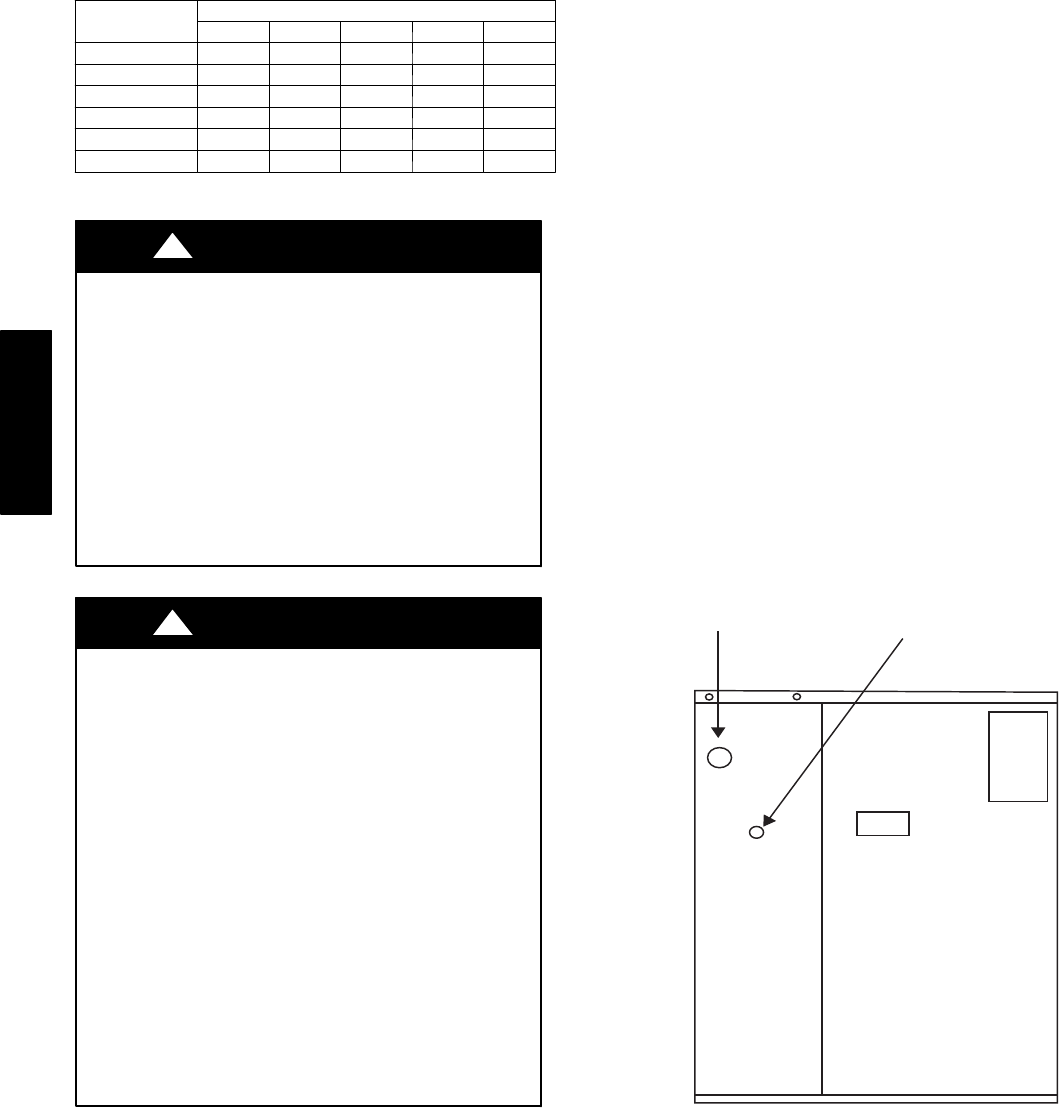
low--voltage entry points are used. See Fig. 6 and 7 for acceptable
location.
Operation of uni t on improper line voltage constitutes abuse and
may cause unit damage tha t coul d affect warranty.
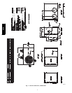
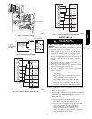
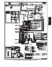
ROUTING POWER LEADS INTO UNIT
Use only copper wire between disconnect and unit. The
high-- voltage leads should be in a conduit until they enter the unit;
conduit termination at the unit must be watertight. Run the
high-- voltage leads through the hole on the control box side of the
unit (See Fig. 7). When the leads are inside the unit, run leads to
the control box (See Fig. 8). For single--phase units, connect leads
to the black and yellow wires (See Fig. 9) .
CONNECTING GROUND LEAD TO UNIT GROUND
Connect the ground lead to the chassis using the unit ground in the
control box (See Fig. 8 and 9).
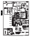
ROUTING CONTROL POWER WIRES (24--V)
Form a drip-- loop with the thermostat leads before routing them
into the unit. Route the thermostat leads through grommeted hole
provided in unit into unit control box (See Fig. 7). Connect
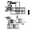
thermostat leads and unit power leads as shown in Fig. 9, 10 and
11.
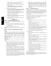
Route thermostat wires through grommet providing a drip-- loop at
the panel. Connect low--voltage leads to the thermostat as shown in
Fig. 10 & 11.
The unit transformer supplies 24--v power for complete system
including accessory electrical heater. Transformer is factory wired
for 230 --v operation.
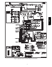
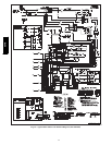
ACCESSORY ELECTRIC HEAT WIRING
Refer to accessory electric heat installation instruc tions for
information on ins talling accessory electric heat. Accessory electric
heat wiring is shown in Fig. 17 and 18.
A08407
Fig. 7 -- Unit Electrical Connection
664B