


—9—
IV. STEP 4 — FIELD FABRICATE DUCTWORK
On vertical units, secure all ducts to roof curb and building
structure. Do not connect ductwork to unit. For horizontal
applications, field-supplied flanges should be attached to
horizontal discharge openings and all ductwork secured to
the flanges. Insulate and weatherproof all external duct-
work, joints, and roof openings with counter flashing and
mastic in accordance with applicable codes.
Ducts passing through an unconditioned space must be
insulated and covered with a vapor barrier.
If a plenum return is used on a vertical unit, the return
should be ducted through the roof deck to comply with appli-
cable fire codes.
A minimum clearance is not required around ductwork. Cab-
inet return-air static pressure (a negative condition) shall
not exceed 0.35 in. wg with economizer or 0.45 in. wg with-
out economizer.
These units are designed for a minimum continuous return-
air temperature in heating of 50 F (dry bulb), or an intermit-
tent operation down to 45 F (dry bulb), such as when used
with a night set-back thermostat.
To operate at lower return-air temperatures, a field-supplied
outdoor-air temperature control must be used to initiate both
stages of heat when the temperature is below 45 F. Indoor
comfort may be compromised when these lower air tempera-
tures are used with insufficient heating temperature rise.
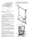
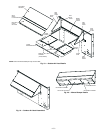
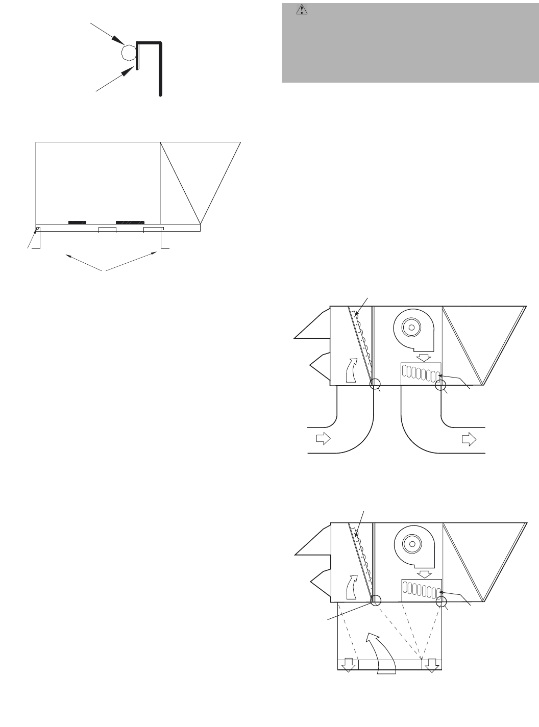
V. STEP 5 — MAKE UNIT DUCT CONNECTIONS
A. Vertical Configuration
Unit is shipped for vertical supply and return duct connec-
tions. Ductwork openings are shown in Fig. 1 and 4. Duct
connections for vertical configuration are shown in Fig. 7.
Field-fabricated concentric ductwork may be connected as
shown in Fig. 8 and 9. The unit is designed to attach the
ductwork to the roof curb. Do not attach duct directly to the
unit.
B. Horizontal Applications
Horizontal units are shipped with outer panels that allow for
side by side horizontal duct connections. If specified during
ordering, the unit will be shipped with the vertical duct
openings blocked off from the factory, ready for side supply
installation. If the horizontal supply/return option was not
specified at time of ordering the unit, a field-installed acces-
sory kit is required to convert the vertical unit into a hori-
zontal supply configuration.
Installation of the duct block-off covers should be completed
prior to placing the unit unless sufficient side clearance is
available. A minimum of 66 in. is required between the unit
and any obstruction to install the duct block-off covers. Side
supply duct dimensions and locations are shown on Fig. 4.
Install ductwork to horizontal duct flange connections on
side of unit.
WARNING: For vertical supply and return units,
tools or parts could drop into ductwork and cause an
injury. Install a 90-degree turn in the return ductwork
between the unit and the conditioned space. If a
90-degree elbow cannot be installed, then a grille of
sufficient strength and density should be installed to
prevent objects from falling into the conditioned space.
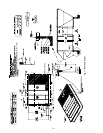
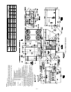
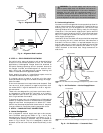
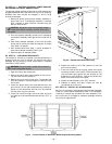
ALIGNMENT
HOLE SHOULD
LINE UP WITH
ROOF CURB
EDGE FLANGE
EDGE FLANGE
ALIGNMENT
HOLE
(IN BASE RAIL)
Fig. 5 — Alignment Hole Details
SUPPLY
OPENING
RETURN
OPENING
ROOF CURB
CURB
SUPPLY
OPENING
CURB
RETURN
OPENING
ALIGNMENT
HOLES FOR
CURB-BOTH
SIDES
Fig. 6 — Alignment Hole Location
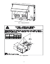
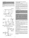
SEE
NOTE
SEE
NOTE
AIR
OUT
AIR
IN
HEAT
EXCHANGER
ECONOMIZER
SEE
NOTE
SEE
NOTE
AIR OUT
AIR IN
HEAT
EXCHANGER
AIR OUT
ECONOMIZER
NOTE: Do not drill in this area; damage to basepan may result in wate
r
leak.
Fig. 7 — Air Distribution — Vertical Supply/Return
NOTE: Do not drill in this area; damage to basepan may result in water
leak.
Fig. 8 — Air Distribution — Concentric Duct