


—38—
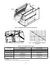
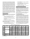
F. Flue Gas Passageways
The flue collector box and heat exchanger cells may be
inspected by removing heat section access panel (Fig. 4), flue
box cover, and main burner assembly (Fig. 30). Refer to Main
Burners section on page 41 for burner removal sequence. If
cleaning is required, clean tubes with a wire brush.
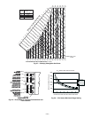
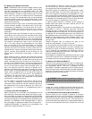
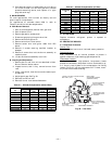
Use caution with ceramic heat exchanger baffles. When
installing retaining clip, be sure the center leg of the clip
extends inward toward baffle. See Fig. 31.
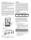
G. Combustion-Air Blower
Clean periodically to assure proper airflow and heating effi-
ciency. Inspect blower wheel every fall and periodically dur-
ing heating season. For the first heating season, inspect
blower wheel bi-monthly to determine proper cleaning
frequency.
To inspect blower wheel, remove heat section panel. Using
an inspection mirror and flashlight, look into the flue
exhaust duct to inspect the wheel. If cleaning is required,
remove motor and wheel assembly by removing the screws
holding the flue box cover to the flue box. See Fig. 30.
Remove the screws holding the inducer housing to the inlet
plate. The wheel can then be removed from the motor shaft
and cleaned with a detergent or solvent. Replace the wheel
onto the motor shaft in the correct position and reassemble
the flue cover onto the flue box.
II. LUBRICATION
A. Compressors
Each compressor is charged with the correct amount of oil at
the factory. Conventional white oil (Zerol 150T or Sontex
SA32) is used. White oil is compatible with 3GS oil, and 3GS
oil may be used if the addition of oil is required. See compres-
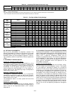
sor nameplate for original oil charge. Oil recharge amount is
shown in Table 1. When a compressor is exchanged in the
field it is possible that a major portion of the oil from the
replaced compressor may still be in the system. While this
will not affect the reliability of the replacement compressor,
the extra oil will add rotor drag and increase power usage. To
remove this excess oil, an access valve may be added to the
lower portion of the suction line at the inlet of the compres-
sor. The compressor should then be run for 10 minutes, shut
down and the access valve opened until no oil flows. This
should be repeated twice to make sure the proper oil level
has been achieved.
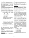
B. Fan Shaft Bearings
Lubricate bearings at least every 6 months with suitable
bearing grease. Typical lubricants are given below:
*Preferred lubricant because it contains rust and oxidation inhibitors.
C. Condenser and Evaporator-Fan Motor Bearings
The condenser and evaporator-fan motors have permanently
sealed bearings, so no field lubrication is necessary.
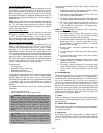
III. EVAPORATOR FAN SERVICE AND REPLACEMENT
The 581A units feature a slide-out fan deck for easy servic-
ing of the indoor-fan motor, pulleys, belt, and bearings. To
service components in this section, perform the following
procedure:
1. Turn off unit power.
2. Open the fan section access panel.
3. Remove three no. 10 screws at front of slide-out fan
deck. Save screws. See Fig. 32.
4. Disconnect the electrical plugs and wires connected
to the slide-out fan deck (evaporator fan plug, supply
air thermistor, and fan status switch if installed).
Wires may be damaged if not disconnected.
5. Fan deck can now be slid out to access serviceable
components.
6. To replace fan deck to operating position, slide fan
deck back into the unit. Secure with the three no. 10
screws removed in Step 3.
7. Re-attach electrical plugs and wires.
8. Close fan section access door.
9. Restore power to unit.
MANUFACTURER LUBRICANT
Texaco Regal AFB-2*
Mobil Mobilplex EP No. 1
Sunoco Prestige 42
Texaco Multifak 2
CAUTION: DO NOT SLIDE FAN DECK OUT
PAST THE STOP BRACKET. If further access is
required, the fan deck must be supported. Make sure
plugs and wiring are not pinched between fan housing
and unit center post. Damage to unit may result.
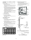
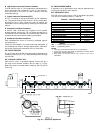
CERAMIC
BAFFLE
CLIP
HEAT
EXCHANGER
SECTION
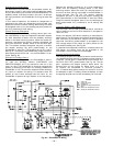
IGC BOARD
(HIDDEN)
COMBUSTION
FAN HOUSING
MAIN BURNER
SECTION
INDUCED
DRAFT
MOTOR
MAIN GAS
VALVE
LEGEND
IGC — Integrated Gas Controller
Fig. 30 — Typical Gas Heating Section
NOTE: One baffle and clip will be in each upper tube of the heat
exchanger.
Fig. 31 — Removing Heat Exchanger Ceramic Baffles
and Clips