


—43—
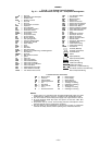
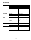
_ _ .A — Circuit A
AHA — Adjustable Heat Anticipator
AL — Ambient Limit
AUX — Auxiliary Contact
_ _ .B — Circuit B
_ _ .C — Circuit C
C—Compressor, Contactor
CAP — Capacitor
CB — Circuit Breaker
CC — Compressor Contactor
CCH — Crankcase Heater
CLO — Compressor Lockout
COMP — Compressor
CR — Compressor Relay
CS — Current Sensor
DU — Dummy Terminal
FCS — Fan Cycling Switch
FIOP — Factory-Installed Option
FPT — Female Pipe Thread
FS — Flame Sensor
FU — Fuse
GND — Ground
GV — Gas Valve
GVR — Gas Valve Relay
HACR — Heating, Air Conditioning, and Refrigeration
HS — Heat Sensor
HERM — Hermetic
HPS — High-Pressure Switch
I—Ignitor
IA — Indoor Air
IAQ — Indoor-Air Quality
IDM — Induced-Draft Motor
IFC — Indoor-Fan Contactor
IFCB — Indoor-Fan Circuit Breaker
IFM — Indoor-Fan Motor
IGC — Integrated Gas Controller
IRH — Indoor Relative Humidity
LAFC — Low Ambient Fan Control
LPS — Low Pressure Switch
LS — Limit Switch
MGV — Main Gas Valve
OA — Outdoor Air
OAS — Outdoor Air Sensor
OAT — Outdoor-Air Temperature
OFC — Outdoor-Fan Contactor
OFM — Outdoor-Fan Motor
ORH — Outdoor Relative Humidity
PEC — Power Exhaust Contactor
PEM — Power Exhaust Motor
PL — Plug
QC — Quadruple Contactor
QT — Quadruple Terminal
RAS — Return Air Sensor
RAT — Return Air Thermostat
RS — Rollout Switch
SAT — Supply-Air Temperature
TB — Terminal Block
TC — Thermostat Cooling
TH — Thermostat Heating
TRAN — Transformer
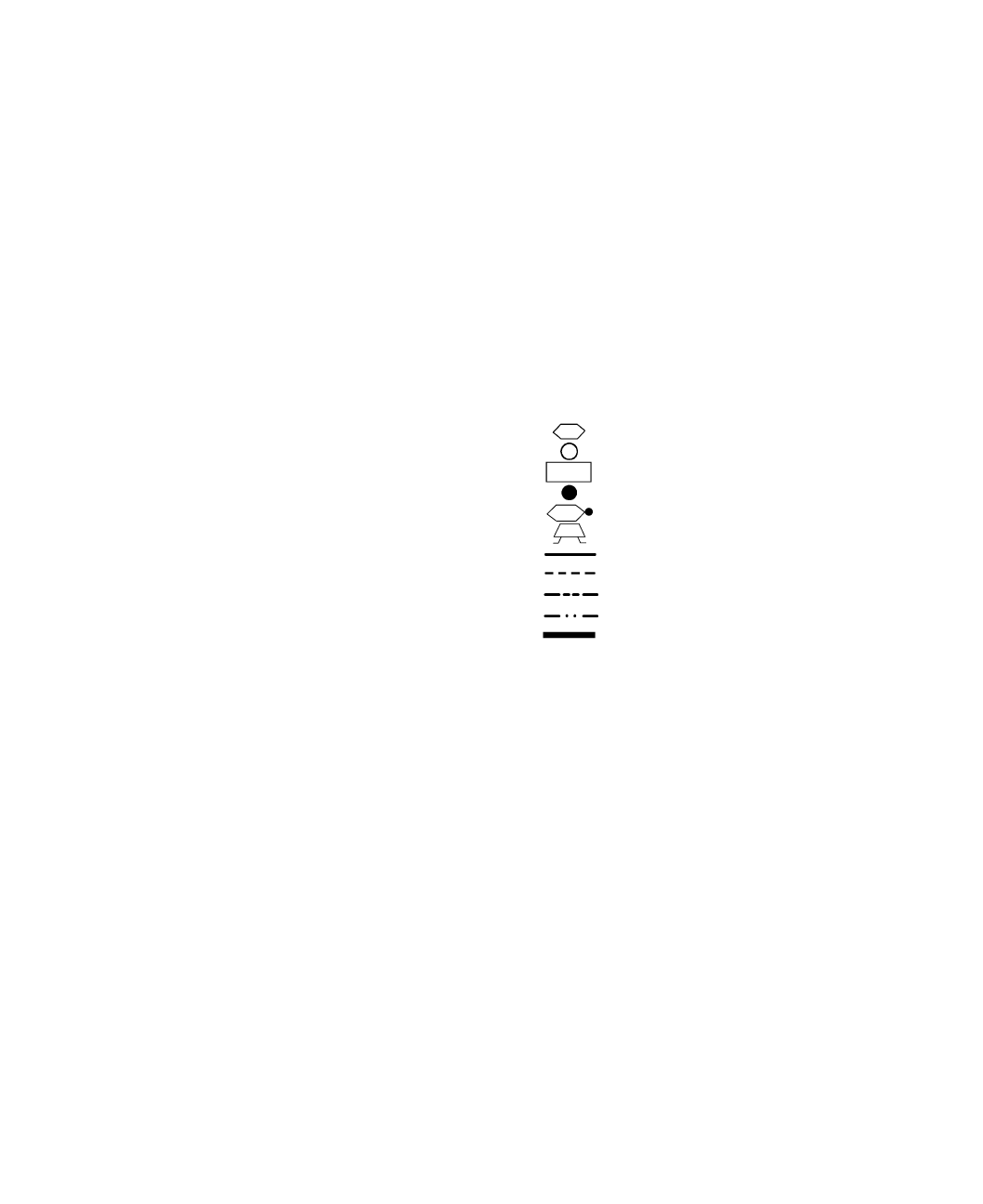
Terminal (Marked)
Terminal (Unmarked)
Terminal Block
Splice
Splice (Marked)
Splice (Field Supplied)
Factory Wiring
Field Control Wiring
Field Power Wiring
Accessory or Optional Wiring
To Indicate Common Potential Only,
Not To Represent Wiring
NOTES:
1. Factory wiring is in accordance with the National Electrical Codes. Any field
modifications or additions must be in compliance with all applicable codes.
2. Use 75 C minimum wire for field power supply. Use copper wires for all units.
3. All circuit breakers “Must Trip Amps” are equal to or less than 156% RLA
(rated load amps).
4. Compressor and fan motors are thermally protected. Three-phase motors
protected against primary single phase conditions.
5. The CLO locks out the compressor to prevent short cycling on compressor
overload and safety devices; before replacing CLO, check these devices.
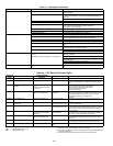
THERMOSTAT/IGC MARKINGS
BM — Blower Motor RS — Rollout Switch
C—Common RT — Power Supply
CM — Inducer Motor SS — Speed Sensor
CS — Centrifugal Switch W—Thermostat Heat
G—Fan W1 — 1st Stage of Heating
GV — Gas Valve W2 — 2nd Stage of Heating
IFO — Indoor Fan On X—Alarm Output
LI — Line I Y1 — 1st Stage of Cooling
R—Thermostat Power Y2 — 2nd Stage of Cooling
LEGEND
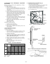
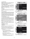
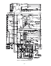
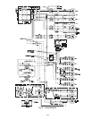
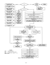
Fig. 40 — Low Voltage Control Schematic
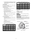
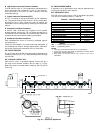
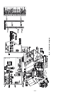
Fig. 41 — Power Schematic and Fig. 42 — Component Arrangement