


—5—
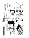
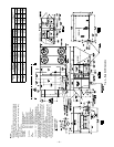
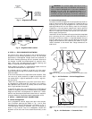
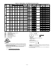
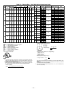
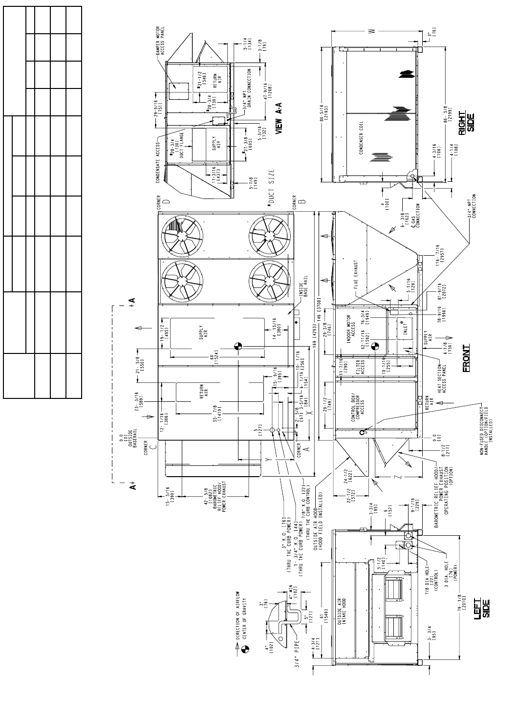
Fig. 4 — Base Unit Dimensions
NOTES:
1. For outdoor use only.
2. Weights shown are for 581A (low heat) unit with manual
25% outdoor air option, aluminum coils, and standard
drive. For weights of optional equipment consult product
data book.
3. Do not locate adjacent units with flue discharge facing
economizer inlet.
Min Clearances to be:
Right Side: 6′-0″ [1829] Condenser Air
Left Side: 10′-0″ [3048] Outside Air
Front Side: 3′-0″ [915] Service
6′-0″ [1829] Condenser Air
8′-0″ [2438] Coil Removal
Rear Side: 6′-0″ [1829] Condenser Air
6′-6″ [1981] Economizer Removal
Top: 6′-0″ [1829] Condenser Fan
Bottom: 1′-2″ [356] Combustible Surface
(Without Curb)
Flue Outlet: 4′-0″ [1219] Combustible Surfaces/
Utility Meters/Regulators/Reliefs
4. For smaller service and operational clearances contact
Bryant Application Engineering Department.
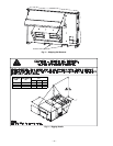
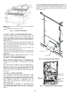
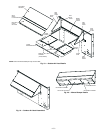
5. Downshot ducts designed to be attached to accessory
roof curb only. If unit is mounted side supply, it is recom-
mended the ducts must be supported by cross braces as
done on accessory roof curb.
6. Dimensions in [ ] are in millimeters.
7. With the exception of clearance for the condenser coil
and the damper/power exhaust as stated in Note #3, a
removable fence or barricade requires no clearance.
8. Dimensions are from outside of base rail. Allow 0
5
/
16
″ [8]
on each side for top cover drip edge.
UNIT SIZE
581A
OPERATING
WEIGHT
(Low Heat Gas)
UNIT HEIGHT CENTER OF GRAVITY LOCATION
CORNER WEIGHT
lb [kg]
WXYZ
lb [kg] in. [mm] in. [mm] in. [mm] in. [mm] A B C D
210 2224 [1008]
58
1
/
8
[1476]
64
1
/
2
[1638]
33
1
/
2
[851]
30
[762]
610
[277]
751
[341]
387
[176]
476
[216]
240 2272 [1030]
58
1
/
8
[1476]
64
[1626]
34
[864]
30
[762]
625
[283]
760
[345]
400
[181]
487
[221]
300 2526 [1146]
70
1
/
8
[1781]
68
[1727]
34
1
/
2
[876]
34
1
/
2
[876]
662
[300]
859
[390]
434
[198]
571
[260]