


—2—
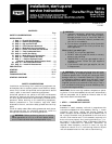
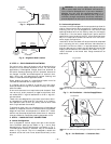
IMPORTANT: The gasketing of the unit to the roof curb is
critical for a watertight seal. Install gasket with the roof
curb as shown in Fig. 1. Improperly applied gasket can also
result in air leaks and poor unit performance. Do not slide
unit to position on roof curb.
B. Alternate Unit Support
When a curb cannot be used, install unit on a noncombusti-
ble surface. Support unit with sleepers, using unit curb
support area. If sleepers cannot be used, support long sides
of unit with a minimum of 3 equally spaced 4-in. x 4-in. pads
on each side.
C. Slab Mount (Horizontal Units Only)
Provide a level concrete slab that extends a minimum of 6 in.
beyond unit cabinet. Install a gravel apron in front of con-
denser coil air inlet to prevent grass and foliage from
obstructing airflow.
NOTE: Horizontal units may be installed on a roof curb if
required.
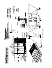
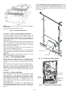
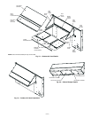
II. STEP 2 — REMOVE SHIPPING RAILS
Remove shipping rails prior to lowering unit onto roof curb.
See Fig. 2. The rails are attached to the unit at both the
return end and condenser end. Remove the screws from both
ends of each rail. Be careful not to drop the rails onto any
surface that could be damaged. Discard the rails. It is impor-
tant to replace the screws into the unit to avoid any air or
water leakage.
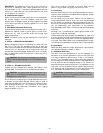
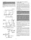
III. STEP 3 — RIG AND PLACE UNIT
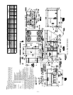
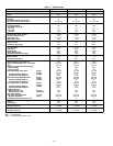
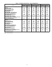
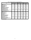
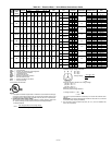
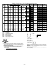
Inspect unit for transportation damage. See Tables 1-3 for
physical data. File any claim with transportation agency.
Do not drop unit; keep upright. Use spreader bars over unit
to prevent sling or cable damage. Rollers may be used to
move unit across a roof. Level by using unit frame as a refer-
ence; leveling tolerance is ±
1
/
16
in. per linear ft in any direc-
tion. See Fig. 3 for additional information. Unit rigging
weight is shown in Fig. 3.
Four lifting holes are provided in the unit base rails as
shown in Fig. 3. Refer to rigging instructions on unit.
A. Positioning
Maintain clearance, per Fig. 4, around and above unit to pro-
vide minimum distance from combustible materials, proper
airflow, and service access.
Do not install unit in an indoor location. Do not locate air
inlets near exhaust vents or other sources of contaminated
air. For proper unit operation, adequate combustion and ven-
tilation air must be provided in accordance with Section 5.3
(Air for Combustion and Ventilation) of the National
Fuel Gas Code, ANSI Z223.1 (American National Standards
Institute).
Although unit is weatherproof, guard against water from
higher level runoff and overhangs.
Locate mechanical draft system flue assembly at least 4 ft
from any opening through which combustion products could
enter the building, and at least 4 ft from any adjacent build-
ing (or per local codes). When unit is located adjacent to pub-
lic walkways, flue assembly must be at least 7 ft above grade.
B. Roof Mount
Check building codes for weight distribution requirements.
Unit operating weight is shown in Table 1.
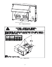
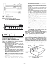
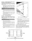
C. Installation Onto Curb
The 581A units are designed to fit on the accessory full
perimeter curb. Correct placement of the unit onto the curb
is critical to operating performance. To aid in correct posi-
tioning,
3
/
8
-in. diameter locating holes have been added to
the unit base rails. When placing the unit, these holes should
line up with the roof curb edge as shown in Fig. 5 and 6, to
assure proper duct opening alignment. For placement on the
roof curb, use the alignment holes located approximately
2-in. from the end of the base rail on the return end of the
unit. See labels on the side of the unit for more details.
CAUTION: Do not allow the shipping rail to drop
on the roof surface. Damage to the roof surface may
result.
CAUTION: All panels must be in place when rig-
ging. Unit is not designed for handling by fork truck.
Damage to unit may result.
CAUTION: Do not slide unit to position it when it
is sitting on the curb. Curb gasketing material may be
damaged and leaks may result.