


—30—
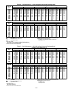
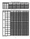
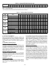
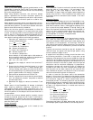
Table 26 — Accessory/FIOP Static Pressure (in. wg)*
LEGEND
*The static pressure must be added to the external static pressure. The sum and the evaporator entering-air cfm should then be
used in conjunction with the Fan Performance tables to determine blower rpm and watts.
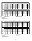
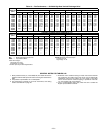
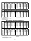
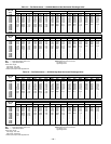
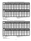
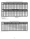
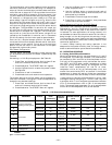
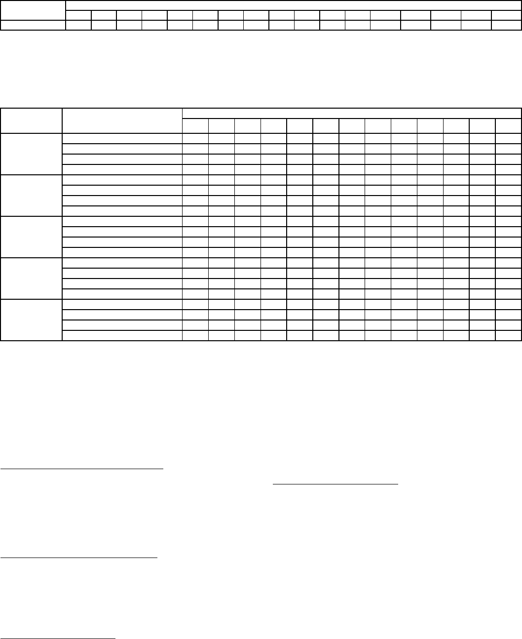
Table 27 — Fan Rpm at Motor Pulley Settings*
*Approximate fan rpm shown.
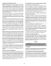
XII. OPTIONAL ECONOMI$ER IV
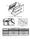
See Fig. 23 for EconoMi$er IV component locations. The
optional EconoMi$er IV comes from the factory fully wired
and assembled. No field wiring or assembly is required for
standard outdoor dry bulb changeover operation. Field wir-
ing of accessory sensors is required for different operational
modes.
A. EconoMi$er IV Standard Sensors
Outdoor Air Temperature (OAT) Sensor
The outdoor air temperature sensor (HH57AC074) is a 10 to
20 mA device used to measure the outdoor-air temperature.
The outdoor-air temperature is used to determine when the
EconoMi$er IV can be used for free cooling. The sensor is
factory-installed on the EconoMi$er IV in the outdoor air-
stream. See Fig. 23. The operating range of temperature
measurement is 40 to 100 F.
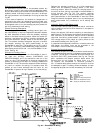
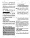
Supply-Air Temperature (SAT) Sensor
The supply-air temperature sensor is a 3 K thermistor
located at the outlet of the indoor fan. See Fig. 24. This sen-
sor is factory installed. The operating range of temperature
measurement is 0° to 158 F.
The temperature sensor is a short probe with blue wires
running to it.
Outdoor Air Lockout Sensor
The EconoMi$er IV is equipped with an ambient tempera-
ture lockout switch located in the outdoor airstream which is
used to lock out the compressors below a 42 F ambient
temperature.
B. EconoMi$er IV Controller Wiring and Operational Modes
Determine the EconoMi$er IV control mode before set up of the
control. Some modes of operation may require different sensors.
Refer to Table 28. The EconoMi$er IV is supplied from the
factory with a supply-air temperature sensor and an
outdoor air temperature sensor. This allows for operation of
the EconoMi$er IV with outdoor air dry bulb changeover
control. Additional accessories can be added to allow for dif-
ferent types of changeover control and operation of the
EconoMi$er IV and unit.
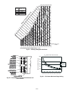
Outdoor Dry Bulb Changeover
The standard controller is shipped from the factory config-
ured for outdoor dry bulb changeover control. The outdoor
air and supply-air temperature sensors are included as
standard. For this control mode, the outdoor temperature is
compared to an adjustable set point selected on the control.
If the outdoor-air temperature is above the set point, the
EconoMi$er IV will adjust the outdoor-air dampers to mini-
mum position. If the outdoor-air temperature is below the set
point, the position of the outdoor-air dampers will be con-
trolled to provide free cooling using outdoor air. When in this
mode, the LED next to the free cooling set point potentiome-
ter will be on. The changeover temperature set point is con-
trolled by the free cooling set point potentiometer located on
the control. The scale on the potentiometer is A, B, C, and D.
See Fig. 25 for the corresponding temperature changeover
values.
COMPONENT
CFM
4,000 4,500 5,000 5,500 6,000 6,500 7,000 7,500 8,000 8,500 9,000 9,500 10,000 10,500 11,000 11,500 12,000
EconoMi$er IV 0.02 0.03 0.04 0.05 0.06 0.07 0.08 0.09 0.10 0.11 0.12 0.13 0.15 0.16 0.17 0.19 0.20
FIOP — Factory-Installed Option
581A
UNIT
SIZE
DRIVE
MOTOR PULLEY TURNS OPEN
0
1
/
2
11
1
/
2
22
1
/
2
33
1
/
2
44
1
/
2
55
1
/
2
6
210
(208/230 and
460 volt)
Low Range Vertical 647 667 687 707 727 747 767 786 806 826 846 866 886
High Range Vertical 897 917 937 958 978 998 1018 1038 1058 1079 1099 1119 1139
Low Range Horizontal 896 924 951 979 1006 1034 1062 1089 1117 1144 1172 1199 1227
High Range Horizontal 1113 1138 1163 1188 1213 1238 1264 1289 1314 1339 1364 1389 1414
210
(575 volt)
Low Range Vertical 810 832 854 876 897 919 941 963 985 1007 1028 1050 1072
High Range Vertical 873 893 912 932 951 971 991 1010 1030 1049 1069 1088 1108
Low Range Horizontal 863 886 909 933 956 979 1002 1025 1048 1072 1095 1118 1141
High Range Horizontal 1042 1062 1083 1103 1123 1143 1164 1184 1204 1224 1245 1265 1285
240
(208/230 and
460 volt)
Low Range Vertical 949 970 992 1013 1035 1056 1078 1099 1120 1142 1163 1185 1206
High Range Vertical 941 961 980 1000 1019 1039 1059 1078 1098 1117 1137 1156 1176
Low Range Horizontal 1113 1138 1163 1188 1213 1238 1264 1289 1314 1339 1364 1389 1414
High Range Horizontal 1096 1116 1137 1157 1177 1197 1218 1238 1258 1278 1299 1319 1339
240
(575 volt)
Low Range Vertical 949 970 992 1013 1035 1056 1078 1099 1120 1142 1163 1185 1206
High Range Vertical 941 961 980 1000 1019 1039 1059 1078 1098 1117 1137 1156 1176
Low Range Horizontal 1113 1138 1163 1188 1213 1238 1264 1289 1314 1339 1364 1389 1414
High Range Horizontal 1096 1116 1137 1157 1177 1197 1218 1238 1258 1278 1299 1319 1339
300
(all voltages)
Low Range Vertical 941 961 980 1000 1019 1039 1059 1078 1098 1117 1137 1156 1176
High Range Vertical 1014 1038 1061 1085 1108 1132 1156 1179 1203 1226 1250 1273 1297
Low Range Horizontal 941 961 980 1000 1019 1039 1059 1078 1098 1117 1137 1156 1176
High Range Horizontal 1014 1038 1061 1085 1108 1132 1156 1179 1203 1226 1250 1273 1297