


—42—
B. High-Pressure and Low-Pressure Switches
If either switch trips, or if the compressor overtemperature
switch activates, that refrigerant circuit will be automati-
cally locked out by the CLO. To reset, manually move the
thermostat setting.
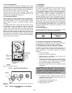
C. Freeze Protection Thermostat (FPT)
An FPT is located on the top and bottom of the evaporator
coil. They detect frost build-up and turn off the compressor,
allowing the coil to clear. Once the frost has melted, the
compressor can be reenergized by resetting the compressor
lockout.
D. Evaporator Fan Motor Protection
A manual reset, calibrated trip, magnetic circuit breaker
protects against overcurrent. Do not bypass connections or
increase the size of the breaker to correct trouble. Determine
the cause and correct it before resetting the breaker.
E. Condenser-Fan Motor Protection
Each condenser-fan motor is internally protected against
overtemperature.
Fuses are also located in the control box and feed power to
the condenser fan motors. Always replace blown fuses with
the correct size fuse as indicated on the unit fuse label.
XIII. RELIEF DEVICES
All units have relief devices to protect against damage from
excessive pressures (i.e., fire). These devices protect the high
and low side.
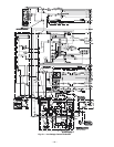
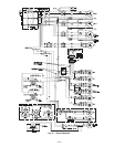
XIV. CONTROL CIRCUIT, 24-V
Each control circuit is protected against overcurrent by a
3.2 amp circuit breaker. Breaker can be reset. If it trips,
determine cause of trouble before resetting. See Fig. 40-42
for wiring.
XV. REPLACEMENT PARTS
A complete list of replacement parts may be obtained from
any Bryant distributor upon request.
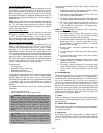
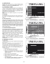
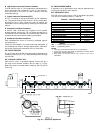
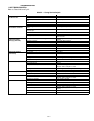
XVI. DIAGNOSTIC LEDs
The IGC control board has a LED for diagnostic purposes.
The IGC error codes are shown in Table 33.
Table 33 — IGC LED Indications
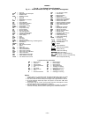
LEGEND
NOTES:
1. There is a 3-second pause between error code displays.
2. If more than one error code exists, all applicable error codes will be
displayed in numerical sequence.
3. Error codes on the IGC will be lost if power to the unit is
interrupted.
ERROR CODE LED INDICATION
Normal Operation On
Hardware Failure Off
Fan On/Off Delay Modified 1 Flash
Limit Switch Fault 2 Flashes
Flame Sense Fault 3 Flashes
Five Consecutive Limit Switch Faults 4 Flashes
Ignition Lockout Fault 5 Flashes
Inducer Switch Fault 6 Flashes
Rollout Switch Fault 7 Flashes
Internal Control Fault 8 Flashes
Software Lockout 9 Flashes
IGC — Integrated Gas Unit Controller
LED — Light-Emitting Diode
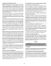
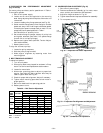
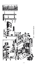
SEE DETAIL “C”
Fig. 39 — Spark Gap Adjustment