


—10—
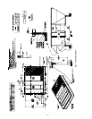
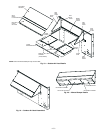
VI. STEP 6 — INSTALL FLUE HOOD AND INLET HOOD
Flue hood (smaller hood), inlet hood (larger hood), and
screens are shipped inside the unit in the fan section. To
install, remove the heat panel. The flue hood is attached to
the heat section panel from the outside using the screws pro-
vided. See Fig. 10.
The inlet hood is installed by inserting the hood through the
back of the heat panel. Attach the hood by inserting the
screws provided through the clearance holes in the heat
panel and into the intake hood.
Install the screens into both hoods using the screws and
retaining nuts provided with the unit.
Attach the cover of the observation hole on the intake hood
and then replace the heat panel onto the unit to complete the
installation.
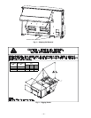
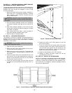
NOTE: When properly installed, the flue hood will line up
with the combustion fan housing. See Fig. 11.
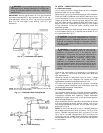
VII. STEP 7 — TRAP CONDENSATE DRAIN
See Fig. 12 for drain location. One
3
/
4
-in. half coupling is pro-
vided outside unit evaporator section for condensate drain
connection. A trap at least 4-in. deep must be used. See
Fig. 13.
All units must have an external trap for condensate drain-
age. Install a trap at least 4 in. deep and protect against
freeze-up. If drain line is installed downstream from the
external trap, pitch the line away from the unit at 1 in. per
10 ft of run. Do not use a pipe size smaller than the unit
connection.
VIII. STEP 8 — INSTALL GAS PIPING
Unit is equipped for use with natural gas. Refer to local
building codes, or in the absence of local codes, to ANSI
(American National Standards Institute) Z223.1-latest year
and addendum Z223.1A-latest year entitled NFGC. In Can-
ada, installation must be in accordance with the
CAN1.B149.1 and CAN1.B149.2 installation codes for gas
burning appliances.
Support gas piping. For example, a
3
/
4
-in. gas pipe must have
one field-fabricated support beam every 8 ft. Therefore, an
18-ft long gas pipe would have a minimum of 3 support
beams.
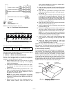
Install field-supplied manual gas shutoff valve with a
1
/
8
-in. NPT pressure tap for test gage connection at unit. The
pressure tap is located on the gas manifold, adjacent to the
gas valve. Field gas piping must include sediment trap and
union. See Fig. 14.
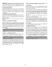
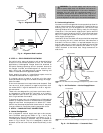
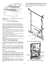
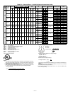
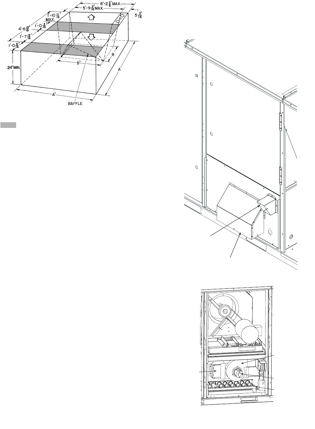
NOTE: Dimensions A, A′, B, and B′ are obtained from field-supplied
ceiling diffuser.
Shaded areas indicate block-off pans.
Fig. 9 — Concentric Duct Details
FLUE HOOD
INLET HOOD
Fig. 10 — Flue and Inlet Hood Locations
MAIN BURNER
SECTION
INDUCED-DRAFT
MOTOR
COMBUSTION
FAN HOUSING
HEAT
EXCHANGER
SECTION
Fig. 11 — Combustion Fan Housing Location