


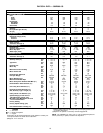
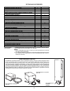
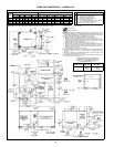
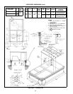
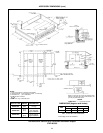
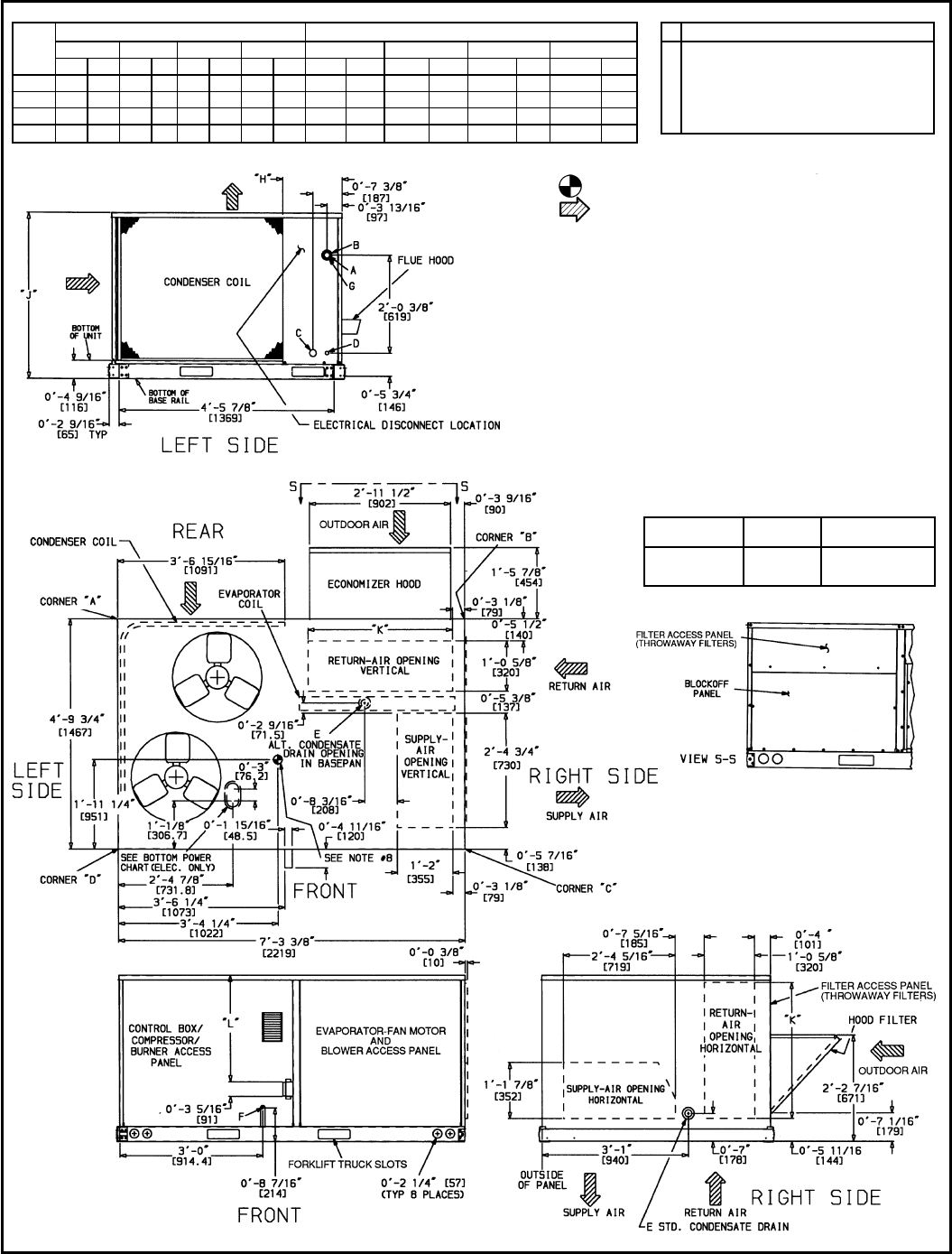
BASE UNIT DIMENSIONS — 580D090-150
UNIT
580D
CORNER WEIGHT* DIMENSIONS
A B C D ‘‘H’’ ‘‘J’’ ‘‘K’’ ‘‘L’’
lb kg lb kg lb kg lb kg ft-in. mm ft-in. mm ft-in. mm ft-in. mm
090 189 86 161 73 239 109 280 127 1-2
7
⁄
8
378 3-5
5
⁄
16
1050 2-9
11
⁄
16
856 2- 2
7
⁄
16
672
102 191 87 163 74 242 110 284 129 3-3
7
⁄
8
1013 3-5
5
⁄
16
1050 2-9
11
⁄
16
856 2- 2
7
⁄
16
672
120 225 102 192 87 285 129 333 151 2-5
7
⁄
8
759 4-1
5
⁄
16
1253 3-0
3
⁄
8
924 2-10
7
⁄
16
875
150 228 103 195 88 289 131 338 153 1-2
7
⁄
8
378 4-1
5
⁄
16
1253 3-0
3
⁄
8
924 2-10
7
⁄
16
875
*Weights are for units only (aluminum plate fins) and do not include options or crating.
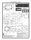
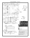
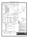
CONNECTION SIZES
A 1
3
⁄
8
Љ Dia [35] Field Power Supply Hole
B 2
1
⁄
2
Љ Dia [64] Power Supply Knockout
C 1
3
⁄
4
Љ Dia [44] Charging Port Hole
D
7
⁄
8
Љ Dia [22] Field Control Wiring Hole
E
3
⁄
4
Љ—14 NPT Condensate Drain
F
1
⁄
2
Љ—14 NPT Gas Connection 090 125 & 102 125
3
⁄
4
Љ—14 NPT Gas Connection All Others
G 2Љ Dia [51] Power Supply Knockout
NOTES:
1. Dimensions in [ ] are in millimeters.
2. Center of gravity.
3. Direction of airflow.
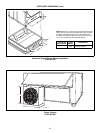
4. Onvertical dischargeunits, ductworkto be attachedto accessoryroof curbonly.
For horizontal discharge units field-supplied flanges should be attached to hori-
zontal discharge openings, and all ductwork should be attached to the flanges.
5. Minimum clearance (local codes or jurisdiction may prevail):
a. Between unit (flue side) and combustible surfaces, 48 inches.
b. Bottom of unit to combustible surfaces (when not using curb) 1 inch.
Bottom of base rail to combustible surfaces (when not using curb) 0 inches.
c. Condenser coil, for proper airflow, 36 in. one side, 12 in. the other. The side
getting the greater clearance is optional.
d. Overhead, 60 in. to assure proper condenser fan operation.
e. Between units, control box side, 42 in. per NEC (National Electrical Code).
f. Between unit and ungrounded surfaces, control box side, 36 in. per NEC.
g. Between unit andblock or concrete walls and other grounded surfaces, con-
trol box side, 42 in. per NEC.
h. Horizontal supply and return end, 0 inches.
6. With the exception of the clearance for the condenser coil and combustion side
as stated in Notes 5a, b, and c, a removable fence or barricade requires no
clearance.
7. Units may be installed on combustible floors made from wood or ClassA, B, or
C roof covering material if set on base rail.
8. The vertical center of gravity is 1Ј-7Љ [483] up from the bottom of the base rail.
Horizontal center of gravity is shown.
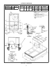
BOTTOM POWER CHART, THESE HOLES
REQUIRED FOR USE WITH ACCESSORY
PACKAGES — CRBTMPWR001A00 (
1
⁄
2
Љ,
3
⁄
4
Љ)
OR CRBTMPWR002A00 (
1
⁄
2
Љ,1
1
⁄
4
Љ)
THREADED
CONDUIT SIZE
WIRE SIZE
REQUIRED HOLE
SIZES (MAX)
1
⁄
2
؆ 24 V
7
⁄
8
Љ [22.2]
3
⁄
4
؆ Power† 1
1
⁄
8
Љ [28.4]
1
1
⁄
4
؆ Power† 1
3
⁄
4
Љ [44.4]
†Select either
3
⁄
4
Љ or 1
1
⁄
4
Љ for power, depending on wire size.
18