


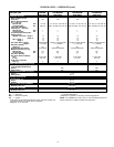
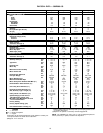
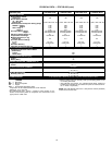
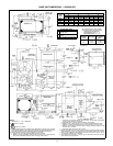
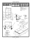
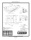
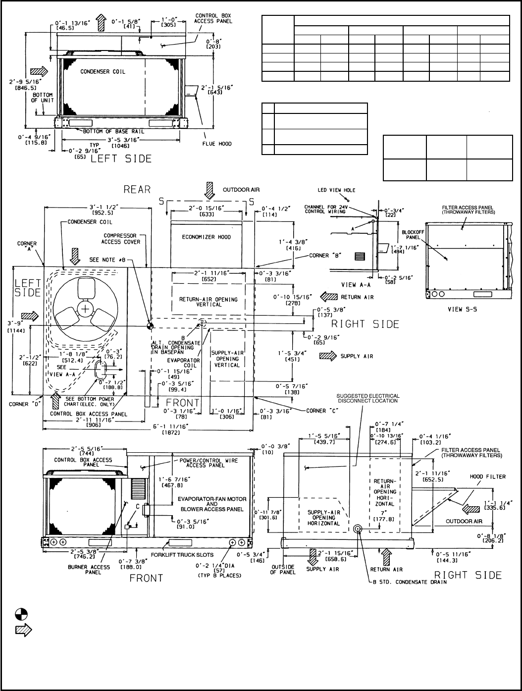
BASE UNIT DIMENSIONS — 580D036-072
UNIT
580D
CORNER WEIGHT*
ABCD
lb kg lb kg lb kg lb kg
036 140 63.5 105 47.6 159 72.1 56 25.4
048 142 64.4 106 48.1 162 73.5 60 27.2
060 150 68.0 115 52.2 160 72.6 65 29.5
072 165 74.8 136 61.7 200 90.7 64 29.0
*Weights are for unit only (aluminum plate fins) and do not include options or crating.
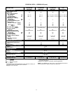
CONNECTION SIZES
A 1
1
⁄
16
Љ Dia. [27] Field Power
Supply Hole
B
3
⁄
4
Љ— 14 NPT Condensate
Drain
C
1
⁄
2
Љ—14 NPT Gas Connection
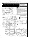
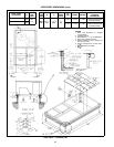
BOTTOM POWER CHART, THESE
HOLES REQUIRED FOR USE WITH
ACCESSORY PACKAGES —
CRBTMPWR001A00 (
1
⁄
2
Љ,
3
⁄
4
Љ)
CRBTMPWR002A00 (
1
⁄
2
Љ,1
1
⁄
4
Љ)
THREADED
CONDUIT
SIZE
WIRE SIZE
REQUIRED
HOLE SIZES
(MAX)
1
⁄
2
؆ 24 V
7
⁄
8
Љ [22.2]
3
⁄
4
؆ Power† 1
1
⁄
8
Љ [28.4]
1
1
⁄
4
؆ Power† 1
3
⁄
4
Љ [44.4]
†Select either
3
⁄
4
Љ or1
1
⁄
4
Љ forpower,depending
on wire size.
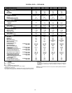
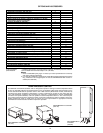
NOTES:
1. Dimensions in [ ] are in millimeters.
2. Center of gravity.
3. Direction of airflow.
4. On vertical discharge units, ductwork to be attached to accessory roof curb only.
For horizontaldischarge units, field-suppliedflanges should beattached to horizon-
tal discharge openings, and all ductwork should be attached to the flanges.
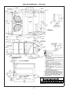
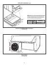
5. Minimum clearance (local codes or jurisdiction may prevail):
a. Between unit, flue side and combustible surfaces, 36 inches.
b. Bottom of unit to combustible surfaces (when not using curb), 1 inch. Bottom of
base rail to combustible surfaces (when not using curb) 0 inches.
c. Condenser coil, for properairflow, 36 in. one side,12 in. the other.The side get-
ting the greater clearance is optional.
d. Overhead, 60 in. to assure proper condenser fan operation.
e. Between units, control box side, 42 in. per NEC (National Electrical Code).
f. Between unit and ungrounded surfaces, control box side, 36 in. per NEC.
g. Between unit and block or concrete walls and other grounded surfaces, control
box side, 42 in. per NEC.
h. Horizontal supply and return end, 0 inches.
6. With the exception of the clearance for the condenser coil and combustion side as
stated in Notes5a, b, and c, a removablefence or barricade requires noclearance.
7. Units may be installed on combustible floors made from wood or Class A, B, or C
roof covering material if set on baserail.
8. The verticalcenter of gravity is 1Ј-6Љ [457] up from thebottom of the base rail. Hori-
zontal center of gravity is shown.
17